Installing cylinder head cover
NOTE:
RISK OF DAMAGE
Contaminant or foreign body
Contamination can result in malfunctions, loss of function or leaks.
Contaminant or foreign body
Contamination can result in malfunctions, loss of function or leaks.
- Adhere to the utmost cleanliness.
- Protect components from contamination e.g. by covering.
- Close off line connections with seal plugs.
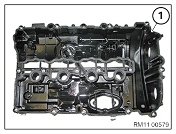
- Replace the profile seal (1).
Parts: Profile seal
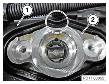
- Make sure that the cylinder head cover (1) is correctly fitted on the high pressure pump bracket (2) in the marked area.
The cylinder head cover (1) must not tap the high pressure pump bracket (2) in the marked area.
NOTE: TECHNICAL INFORMATION
When assembling, it is essential to observe screwing sequences and tightening torques.
Failure to comply with the regulations can lead to leaks and damage. - Position cylinder head cover.
- Make sure that the cylinder head cover does not tap the high pressure pump bracket.
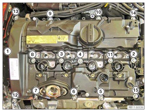
- Join all screws of the cylinder head cover in sequence (1) to (15) in 180 degree steps.
- Tighten the screws of the cylinder head cover in sequence (1) to (15).TIGHTENING TORQUES SPECIFICATION
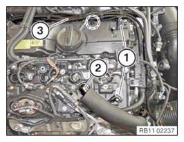
Cylinder head cover to cylinder head M6 Joining torque: 8 Nm Tightening torque: 11 Nm - Position the fuel supply line and tighten the screw (4).TIGHTENING TORQUES SPECIFICATION
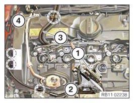
Fuel delivery line to cylinder head cover Tightening torque: 6.5 Nm - Position the engine wiring harness (3) and clip in the marked area.
- Clip in the cable in the marked areas.
- Position the carrier plate and tighten the screw (2).
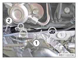
- Clip in both oxygen sensor connectors (1) on the carrier plate.
- Correctly route the engine wiring harness (3) and clip in the highlighted area.
- Clip in the engine ventilation line (2).
- Connect and lock both connectors (1).
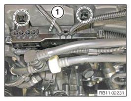
- Clip in the positive battery cable (2) in the highlighted area.
- Attach both oxygen sensor cables (1) in the highlighted areas.
- Clip in the engine wiring harness (1) in the highlighted areas.
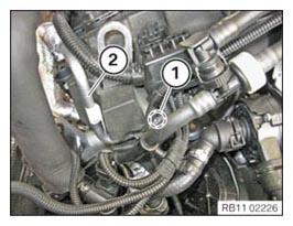
- Replace the O-ring of the oil feed line (2).
Parts: O-ring
- Position oil feed line (2).
- Tighten down screw (1).TIGHTENING TORQUES SPECIFICATION
Oil feed line on cylinder head M6x12
Replace O-ring.Tightening torque: 8 Nm
Follow-up work:
- Refer to PREPARING THE INJECTORS FOR INSTALLATION .
- Refer to INSTALLING INJECTORS .
- Refer to INSTALLING HIGH PRESSURE PUMP .
- Refer to INSTALLING FUEL DELIVERY LINE .
- Refer to INSTALLING THE HIGH-PRESSURE LINE BETWEEN THE HIGH-PRESSURE PUMP AND THE HIGH-PRESSURE RAIL .
- Refer to INSTALLING THE IGNITION COILS .
- Refer to INSTALLING BOTH ACTUATORS .
- Refer to INSTALLING CENTER BULKHEAD LOWER SECTION .
- Refer to LOOSENING HIGH-VOLTAGE CABLES ON THE ELECTRICAL MACHINE ELECTRONICS .
- Refer to INSTALLING RIGHT SEALING FRAME .
- Refer to INSTALLING LEFT SEALING FRAME .
- Refer to INSTALLING FRONT ENGINE ENCAPSULATION .
- Refer to INSTALLING AUXILIARY COOLANT PUMP FOR THE EXHAUST TURBOCHARGER .
- Refer to INSTALLING THE ACOUSTIC COVER FOR THE ENGINE AT THE FRONT .
- Refer to CONNECTING THE COOLANT LINE OF HIGH-TEMPERATURE COOLANT CIRCUIT .
- Refer to FILLING THE HIGH-TEMPERATURE COOLING SYSTEM WITH THE VACUUM FILLER DEVICE .
- Refer to INSTALLING THE CENTER BULKHEAD UPPER PART .
- Refer to INSTALLING TRAILING LINK AT SPRING STRUT DOME .
- Refer to INSTALLING COWL PANEL COVER .
- Refer to INSTALLING LEFT AND RIGHT WIPER ARM .
- Refer to INSTALLING THE COVER OF THE ENGINE COMPARTMENT ON THE REAR LEFT .
- Refer to INSTALLING ACOUSTIC COVER AT REAR .
- Refer to INSTALLING THE SEAL FOR THE BONNET .
- Refer to INSTALLING CHARGE AIR LINE .
- Refer to INSTALLING CLEAN AIR PIPE .
- Refer to INSTALLING RESONATOR .
- Refer to INSTALLING THE ACOUSTIC COVER FOR THE ENGINE AT THE FRONT .
- Refer to INSTALLING INTAKE SILENCER HOUSING .
- Refer to INSTALLING ACOUSTIC COVER .
- Refer to BLEEDING THE HIGH-TEMPERATURE COOLANT CIRCUIT .
- Refer to INSTALLING THE UNDERBODY PROTECTION OF THE STEERING GEAR OR THE FRONT STIFFENING PLATE .
- Refer to INSTALLING FRONT UNDERBODY PROTECTION AND/OR FRONT STIFFENING PLATE .