Installing the left cylinder head cover
NOTE:
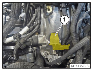
Make sure that there are no particles or impurities in the medium openings. Coolant or foreign substances in the oil can cause engine damage such as damage to the connecting rod bearing.
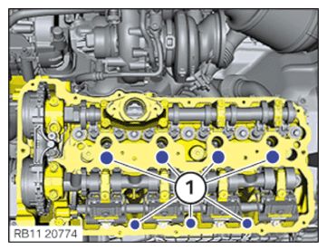
- Close the openings (1) on the cylinder head.
NOTE:
RISK OF DAMAGE
Damage to the surface.
The use of metal-cutting tools (e.g., emery cloths) for cleaning surfaces can damage them and lead to leaks and/or engine damage.
Damage to the surface.
The use of metal-cutting tools (e.g., emery cloths) for cleaning surfaces can damage them and lead to leaks and/or engine damage.
- Do not use any metal-cutting tools.
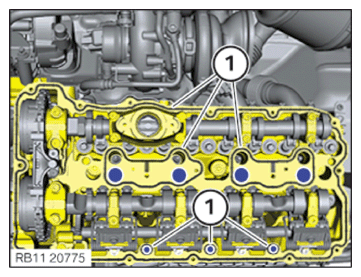
- Clean the cylinder head in the area of the sealing surfaces (1).
- Open the openings (1) on the cylinder head.
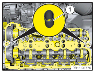
- Make sure the fitting sleeves (1) are installed.
The fitting sleeves must not be damaged or deformed.
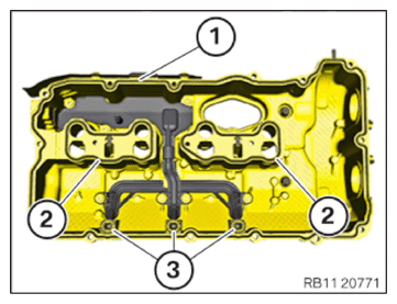
- Replace the circular seal (1).
Parts: Gasket
- Replace seals (2).
Parts: Seals
- Replace seals (3).
Parts: Seals
Tightening the screws of the left cylinder head cover
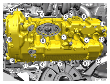
Screwing sequence of the left cylinder head cover
NOTE:
The sealing surfaces must be free of oil, grease and cleaning agents.
- Insert and position the cylinder head covers.
- Abut bolts (10) and (15).
The layout of screws (10) and (15) is required for exact positioning of the camshaft position sensors.
- Tighten screws in the order (1) to (17).
TIGHTENING TORQUES SPECIFICATION
| Cylinder head cover to cylinder head | ||
| M6x30 screw | Tightening torque | 10 Nm |
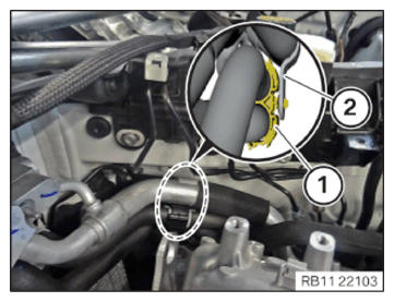
- Clip in the holder of the coolant hoses (1) on the refrigerant line (2).
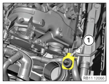
- Mount the bracket for the charge air cooler.
- Tighten down screw (1).TIGHTENING TORQUES SPECIFICATION
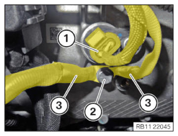
Charge air cooler holder on cylinder head cover M6x18 tightening torque 8 Nm - Position the grounding cables (3).
- Tighten down screw (2).TIGHTENING TORQUES SPECIFICATION
Ground connection on cylinder head cover M6x14 screw tightening torque 10 Nm - Connect connectors (1) and lock.
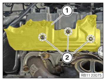
- Clip in the holder (1).
- Position the heat shield (2).
- Tighten down screws (1).
TIGHTENING TORQUES SPECIFICATION
| Heat protection plate | ||
| M6x12 screw Replace screw. |
tightening torque | 10 Nm |
Follow-up work
- Refer to INSTALLING VANOS SOLENOID ACTUATOR, INTAKE OF CYLINDER BANK 2 .
- Refer to INSTALLING THE VANOS SOLENOID ACTUATOR EXHAUST OF CYLINDER BANK 2 .
- Refer to INSTALLING THE LEFT HIGH PRESSURE PUMP .
- Refer to INSTALLING FUEL DELIVERY LINE .
- Refer to INSTALLING THE INJECTORS FOR THE CYLINDERS 5 TO 8 .
- Refer to INSTALLING THE HIGH-PRESSURE RAIL ON THE LEFT .
- Refer to INSTALLING THE IGNITION COILS OF CYLINDER BANK 2 .
- Refer to INSTALLING THE IGNITION COILS OF CYLINDERS 1 AND 5 .
- Refer to INSERT THE EXHAUST TURBOCHARGER FOR THE CYLINDERS 5 TO 8 .
- Refer to INSTALLING THE CLEAN AIR PIPE OF CYLINDER BANK 2 .
- Refer to INSTALLING CLEAN AIR PIPE OF CYLINDER BANK 1 .
- Refer to INSTALLING BOTH CHARGE AIR COOLERS .
- Refer to CONNECTING THE RIGHT CHARGE AIR LINE TO THE EXHAUST TURBOCHARGER .
- Refer to CONNECTING THE LEFT CHARGE AIR LINE TO THE EXHAUST TURBOCHARGER .
- Refer to CLOSING THE HIGH-TEMPERATURE COOLANT CIRCUIT .
- Refer to INSTALLING THE COOLANT EXPANSION TANK FOR THE LOW-TEMPERATURE COOLANT CIRCUIT (CHARGE AIR COOLER) .
- Refer to SEALING OFF COOLANT FOR LOW-TEMPERATURE COOLANT CIRCUIT .
- Refer to INSTALLING THE UNDERBODY PROTECTION OF THE STEERING GEAR OR THE FRONT THRUST FIELD .
- Refer to INSTALLING THE FRONT UNDERBODY PROTECTION OR FRONT STIFFENING PLATE (THRUST FIELD) .
- Refer to INSTALLING THE FRONT LEFT BOTTOM WHEEL ARCH COVER .
- Refer to INSTALLING THE FRONT BOTTOM RIGHT WHEEL ARCH COVER .
- Refer to INSTALLING DRIVE BELT .
- Refer to INSTALLING FAN COWL .
- Refer to INSTALLING THE REAR TOP CROSS CONNECTION .
- Refer to INSTALLING FRONT CROSS CONNECTION .
- Refer to INSTALLING THE RIGHT INTAKE FILTER HOUSING WITH THE RIGHT FRONT-END STRUT .
- Refer to INSTALLING LEFT INTAKE FILTER HOUSING WITH LEFT FRONT-END STRUT .
- Refer to INSTALLING THE COVER ON THE LEFT AND RIGHT IN THE ENGINE COMPARTMENT AT THE TOP .
- Refer to INSTALLING THE CATALYTIC CONVERTER FOR CYLINDERS 5 TO 8 .
- Refer to RELEASING THE HEAT SHIELD .
- Refer to INSTALLING THE CENTER COWL UPPER PART .
- Refer to INSTALLING TENSION STRUT ON SHOCK TOWER .
- Refer to INSTALLING WINDSHIELD PANEL COVER .
- Refer to INSTALLING LEFT AND RIGHT WIPER ARM .
- Refer to INSTALLING THE REAR RIGHT ENGINE COMPARTMENT COVER .
- Refer to INSTALLING THE COVER OF THE ENGINE COMPARTMENT ON THE REAR LEFT .
- Refer to INSTALLING RIGHT HEAT SHIELD .
- Refer to INSTALLING LEFT HEAT SHIELD .
- Refer to INSTALLING HEAT SHIELD, TOP .
- Refer to INSTALLING THE RIGHT OXYGEN SENSOR MONITOR .
- Refer to INSTALLING THE LEFT OXYGEN SENSOR MONITOR .
- Refer to PARTIALLY INSTALLING THE RIGHT LAMBDA OXYGEN SENSOR .
- Refer to PARTIALLY INSTALLING THE LEFT LAMBDA OXYGEN SENSOR .
- Refer to INSTALLING THE RETAINING BRIDGE IN VEHICLES WITH A GASOLINE PARTICULATE FILTER .
- Refer to INSTALLING THE RETAINING BRIDGE .
- Refer to INSTALLING EXHAUST SYSTEM .
- Refer to INSTALLING CENTER REAR UNDERSHIELD .
- Refer to INSTALLING THE CONNECTING SUPPORTS ON THE TUNNEL .
- Refer to INSTALLING THE CONTROL UNIT BRACKET FOR CYLINDERS 5 TO 8 .
- Refer to INSTALLING THE COVER OF THE LEFT DME CONTROL UNIT .
- Refer to INSTALLING CONTROL UNIT HOLDER FOR CYLINDERS 1 TO 4 .
- Refer to INSTALLING THE COVER OF THE RIGHT DME CONTROL UNIT .
- Refer to CONNECTING NEGATIVE BATTERY CABLE
- Refer to FILLING AND VENTING THE LOW-TEMPERATURE COOLANT CIRCUIT .
- Refer to FILLING AND VENTING THE HIGH-TEMPERATURE COOLANT CIRCUIT .