Removing the piston with connecting rod
Prerequisite
- Remove and install front axle complete with engine and transmission.
Remove and install the engine on the front axle
WARNING:
Working on fuel system.
Risk of fire! Danger of explosion!
Risk of fire! Danger of explosion!
- When working on the fuel system, make sure the workstation has sufficient ventilation, e.g., by means of extraction.
- Tightly seal off open lines and connections; collect any leakage fuel directly at the point of exit.
- No fire, sparks, open flames or smoking.
NOTE:
TECHNICAL INFORMATION
Collect and dispose of emerging fluids. Observe country-specific waste disposal regulations.
Collect and dispose of emerging fluids. Observe country-specific waste disposal regulations.
Preliminary work
- Refer to MOUNTING THE ENGINE TO THE ENGINE SUPPORT BRACKET .
- Refer to RELEASING THE OIL DRAIN PLUG .
- Refer to REMOVE DRIVE BELT .
- Refer to REMOVING THE BELT TENSIONER .
- Refer to REMOVING THE BELT PULLEY ON THE TORSIONAL VIBRATION DAMPER .
- Refer to REMOVING THE COOLANT PUMP .
- Refer to RELEASING LEFT CHARGE AIR LINE PARTIALLY .
- Refer to PARTIALLY RELEASING THE RIGHT CHARGE AIR LINE .
- Refer to REMOVE THE COOLANT EXPANSION TANK FOR THE LOW-TEMPERATURE COOLANT CIRCUIT (CHARGE AIR COOLER) .
- Refer to REMOVE BOTH CHARGE AIR COOLERS .
- Refer to REMOVE THE CLEAN AIR PIPE OF CYLINDER BANK 1 .
- Refer to REMOVE THE CLEAN AIR PIPE OF CYLINDER BANK 2 .
- Refer to REMOVING THE IGNITION COILS OF CYLINDERS 1 AND 5 .
- Refer to REMOVING FUEL DELIVERY LINE .
- Refer to REMOVING IGNITION COIL OF CYLINDER BANK 2 .
- Refer to REMOVE LEFT HIGH PRESSURE PUMP .
- Refer to REMOVE THE HIGH-PRESSURE RAIL ON THE LEFT .
- Refer to REMOVE THE INJECTORS FOR CYLINDERS 5 TO 8 .
- Refer to REMOVING VANOS SOLENOID ACTUATOR, EXHAUST OF CYLINDER BANK 2 .
- Refer to REMOVING VANOS SOLENOID ACTUATOR, INTAKE OF CYLINDER BANK 2 .
- Refer to REMOVING THE LEFT AND RIGHT EXHAUST TURBOCHARGER .
- Refer to REMOVING FRONT HEAT SHIELD .
- Refer to REMOVING THE OIL FEED LINE AT THE EXHAUST TURBOCHARGER FOR CYLINDERS 5 TO 8 .
- Refer to REMOVE LEFT CYLINDER HEAD COVER .
- Refer to REMOVE THE SEALING CAP ON THE CYLINDER HEAD OF THE CYLINDER BANK 2 .
- Refer to MOVING THE CRANKSHAFT TO THE INSTALLATION POSITION TO ADJUST THE TIMINGS .
- Refer to CHECK THE VANOS ADJUSTER OF CYLINDER BANK 2 .
- Refer to RELAXING CHAIN TENSIONER ON BANK 2 FOR CHECKING OR SETTING TIMING .
- Refer to REMOVING HYDRAULIC CHAIN TENSIONER OF CYLINDER BANK 2 .
- Refer to PRELOADING THE TIMING CHAIN OF CYLINDER BANK 2 .
- Refer to FIXING THE ENGINE IN THE INSTALLATION POSITION ON CYLINDER 1 (SET VALVE TIMINGS) .
- Refer to REMOVING BOTH LEFT VANOS ADJUSTERS .
- Refer to REMOVING SPECIAL TOOL FOR FIXING CAMSHAFTS IN POSITION ON BANK 2 .
- Refer to REMOVING SPECIAL TOOL TO PRETENSION TIMING CHAIN ON CYLINDER BANK 2 .
- Refer to REMOVE LEFT CYLINDER HEAD .
- Refer to REMOVING IGNITION COIL OF CYLINDER BANK 1 .
- Refer to REMOVE RIGHT HIGH-PRESSURE PUMP .
- Refer to REMOVE RIGHT RAIL .
- Refer to REMOVE THE INJECTORS FOR CYLINDERS 1 TO 4 .
- Refer to PARTIALLY RELEASING THE GUIDE TUBE FOR THE OIL DIPSTICK .
- Refer to REMOVING VANOS SOLENOID ACTUATOR, EXHAUST OF CYLINDER BANK 1 .
- Refer to REMOVE THE VANOS SOLENOID ACTUATOR INTAKE OF CYLINDER BANK 1 .
- Refer to REMOVE RIGHT CYLINDER HEAD COVER .
- Refer to REMOVE THE SEALING CAP ON THE CYLINDER HEAD OF THE CYLINDER BANK 1 .
- Refer to CHECKING THE VANOS ADJUSTER OF CYLINDER BANK 1 .
- Refer to RELIEVING THE CHAIN TENSIONER AT CYLINDER BANK 1 FOR CHECKING OR SETTING THE VALVE TIMINGS .
- Refer to REMOVING HYDRAULIC CHAIN TENSIONER OF CYLINDER BANK 1 .
- Refer to PRELOADING THE TIMING CHAIN OF CYLINDER BANK 1 .
- Refer to FIXING THE ENGINE IN THE INSTALLATION POSITION ON CYLINDER 1 (SET VALVE TIMINGS) .
- Refer to REMOVING BOTH RIGHT VANOS ADJUSTERS .
- Refer to REMOVING SPECIAL TOOL FOR FIXING CAMSHAFTS ON BANK 1 .
- Refer to REMOVING THE SPECIAL TOOL TO PRETENSION THE TIMING CHAIN AT CYLINDER BANK 1 .
- Refer to REMOVE RIGHT CYLINDER HEAD .
- Refer to REMOVING THE VIBRATION DAMPER .
- Refer to REMOVE LOWER OIL PAN SECTION .
- Refer to REMOVE OIL PUMP .
- Refer to REMOVE FRONT AXLE DIFFERENTIAL .
- Refer to REMOVING THE OIL FILTER ELEMENT
- Refer to REMOVING UPPER OIL SUMP SECTION, ENGINE REMOVED .
NOTE:
TECHNICAL INFORMATION
Piston, piston pin, connecting rod and connecting rod bearing shells are matched to each other and balanced.
Always install the pistons, piston pins, connecting rods and connecting rod bearing shells in the cylinder from which they were removed.
Piston, piston pin, connecting rod and connecting rod bearing shells are matched to each other and balanced.
Always install the pistons, piston pins, connecting rods and connecting rod bearing shells in the cylinder from which they were removed.
NOTE:
The description is for one component only. The procedure is identical for all further components.
NOTE:
TECHNICAL INFORMATION
The work must be performed with vehicle care to prevent component damage.
The work must be performed with vehicle care to prevent component damage.
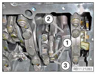
- Twist the crankshaft (2) into the position for disassembly.
- Unscrew both connecting rod bolts (1).
- Remove the connecting rod bearing cap (3) with guide bearing shell.
NOTE:
TECHNICAL INFORMATION
For installation and dismantling of the connecting rods, it is essential for the crankshaft to be exactly in alignment with the cylinder bore.
For installation and dismantling of the connecting rods, it is essential for the crankshaft to be exactly in alignment with the cylinder bore.
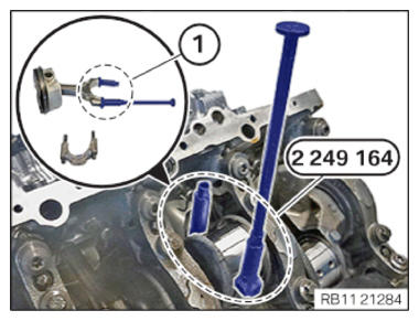
- Screw in the special tools 2 249 164 hand-tight into the threaded connection of the connecting rod bolts (1).
- Press the piston with the connecting rod out toward the bottom with the special tool 2 249 164.
NOTE:
RISK OF DAMAGE
Damage on the cylinder wall and oil spray nozzles.
A large force can scratch the cylinder wall and bend the oil spray nozzles.
Damage on the cylinder wall and oil spray nozzles.
A large force can scratch the cylinder wall and bend the oil spray nozzles.
- Carefully shift the piston and connecting rod in the engine block.
- Remove the piston and connecting rod in an upward direction.
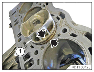
- Lever the connecting rod bearing shell (1) out of the connecting rod bearing cap (see arrows).
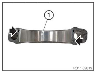
- (1) Lever out Irox-coated bearings from the connecting rod (see arrows).
NOTE:
The description is for one component only. The procedure is identical for all further components.
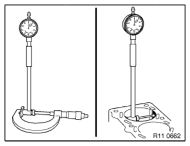
- Measure the cylinder path.
TECHNICAL DATA - CYLINDER SPECIFICATION
| Engine in general, bore | ||
|---|---|---|
| +0 | ||
| 89.014 | mm | |
| -0.01 | ||
TECHNICAL DATA - PISTON SPECIFICATION
| Piston installation clearance (piston new) | ||
|---|---|---|
| Piston installation clearance (piston new) | 0.003... | 0.023 mm |
TECHNICAL DATA - PISTON SPECIFICATION
| Permissible total wear tolerance between piston and cylinder (engine operated) | |
|---|---|
| Piston installation clearance (piston worn) | 0.25 mm |
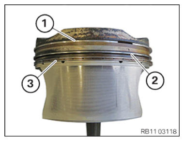
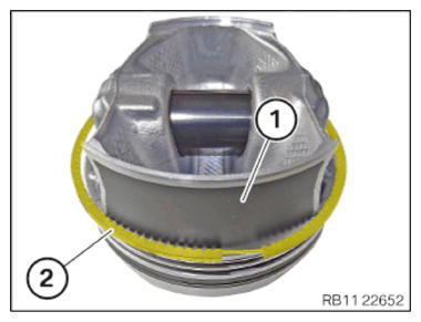
- Check the arrangement of the piston rings.
Piston ring (1).
Piston ring (2).
Oil scraper ring (U-Flex design) (3).
Check
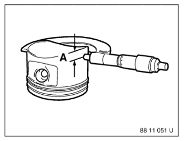
- Position micrometer in area (A) and measure piston installation clearance transversely to piston pin.
TECHNICAL DATA - PISTON DIAMETER SPECIFICATION
| Piston diameter | ||
|---|---|---|
| Measure the piston diameter at distance (A) from the lower end of the piston skirt. | Distance (A) to the lower end of the piston skirt | |
| 18 mm | ||
| Nominal dimension of piston diameter | ||
| +0.02 | ||
| 88.987-0 02 | mm | |
Result
» Piston does not correspond to the specifications.
Measure
- Replace piston.
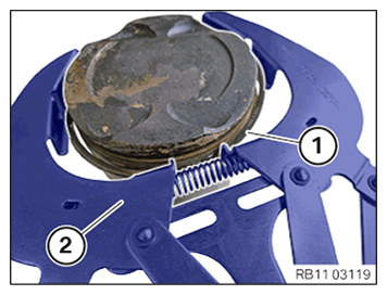
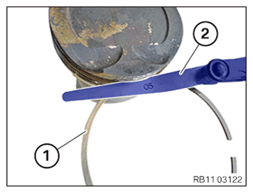
- Remove upper and middle piston ring (1) with a piston ring pliers (2).
- Remove oil scraper ring (2) (U-Flex) by hand over the piston skirt (1).
- Compare and evaluate the side clearance values with the setpoint values.
- Clean the ring zone on the piston.
- Insert the piston ring into the annular groove on the piston.
Determine side clearance values with a feeler gauge (1).
TECHNICAL DATA - CLEARANCE PISTON RING SPECIFICATION
| Piston ring 1st groove A | |
|---|---|
| Side clearance. | 0.02... 0.07 mm |
TECHNICAL DATA - GROOVE HEIGHT PISTON RING SPECIFICATION
| Piston ring 1st groove H | |
|---|---|
| Annular groove height. | 1.21... 1.24 mm |
TECHNICAL DATA - CLEARANCE PISTON RING SPECIFICATION
| Piston ring 2nd groove A | |
|---|---|
| Side clearance. | 0.015... 0.06 mm |
TECHNICAL DATA - GROOVE HEIGHT PISTON RING SPECIFICATION
| Piston ring 2nd groove H | |
|---|---|
| Annular groove height. | 1.51... 1.53 mm |
TECHNICAL DATA - GROOVE HEIGHT PISTON RING SPECIFICATION
| Piston ring 3rd groove H | |
|---|---|
| Annular groove height. | 2.01... 2.03 mm |
TECHNICAL DATA - CLEARANCE PISTON RING SPECIFICATION
| Piston ring 3. Groove-A DSF ring | |
|---|---|
| Side clearance without spiral expander. | 0.02... 0.06 mm |
TECHNICAL DATA - CLEARANCE PISTON RING SPECIFICATION
| Piston ring 3. Groove-A U-flex ring | |
|---|---|
| Side clearance without spiral expander. | 0.02... 0.08 mm |
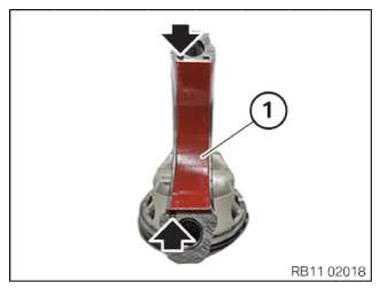
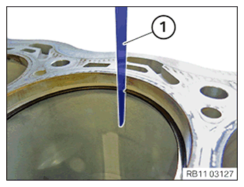
- Use the piston (1) to push the upper and center piston ring in parallel to the last annular groove (see graphic).
- Determine the end clearance, compare to the setpoint value and assess.
NOTE:
The description is for one component only. The procedure is identical for all further components.
- Determine the gap on the piston ring (end clearance) with a suitable feeler gauge (1).
If applicable, replace the piston rings.
TECHNICAL DATA - CLEARANCE PISTON RING SPECIFICATION
| Piston ring 1st groove S | |
|---|---|
| End clearance. | 0.15... 0.30 mm |
TECHNICAL DATA - CLEARANCE PISTON RING SPECIFICATION
| Piston ring 2nd groove S | |
|---|---|
| End clearance. | 0.30... 0.50 mm |