Adjust the timing for cylinder 5 to 8 (cylinder head removed)
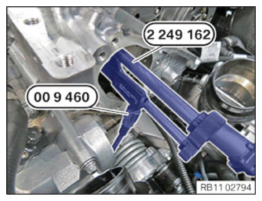
- Pretension timing chain with special tool 2 249 162 .
- Adjust special tool 0 496 778 (00 9 460)
to 0.6 Nm.
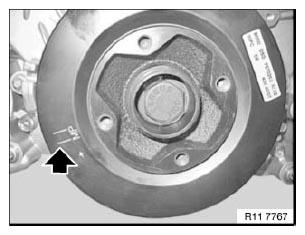
- Observe the MP identification.
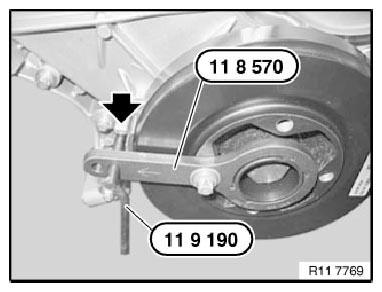
The identification MP (= installation position) is important for the installation of the special tool 0 496 366 (11 8 570) .
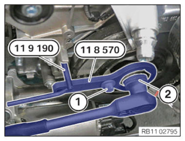
- Position the special tool 0 496 366 (11 8 570) on the vibration absorber and secure it with the bolt (1).
- Insert special tool 0 493 882 (11 9 190) into the crankcase.
- Crank the crankshaft on the central bolt using a reversible ratchet (2) in the direction of engine rotation until it is in contact with special tool 0 493 882 (11 9 190)
.
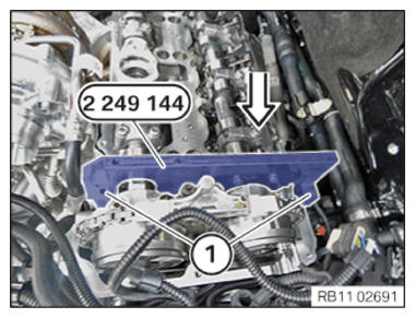
- Position special tool 2 249 144 on the intake camshaft of bank 1 - 4 in the direction of the arrow and secure with one screw (1) each.
TIGHTENING TORQUES SPECIFICATION
| Special tool, gauge to cylinder head | ||
|---|---|---|
| M6x35 | Tightening torque | 10 Nm |
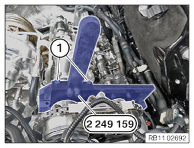
- Position the special tool 2 249 159 on the exhaust camshaft and screw it to special tool 2 249 144 .
TIGHTENING TORQUES SPECIFICATION
| Special tool to special tool, gauges | ||
|---|---|---|
| M6x20 | Tightening torque | 10 Nm |
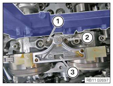
- Position the slide rail (3).
- Insert the screws (1) and (2).
TIGHTENING TORQUES SPECIFICATION
| Sliding rail to cylinder head | ||
|---|---|---|
| M6x67 M6x48 | Tightening torque | 10 Nm |
- Position the special tool 0 496 366 (11 8 570) on the vibration absorber and secure it with the bolt (1).
- Insert special tool 0 493 882 (11 9 190) into the crankcase.
- Crank the crankshaft on the central bolt using a reversible ratchet (2) in the direction of engine rotation until it is in contact with special tool 0 493 882 (11 9 190)
.
- Secure the VANOS central valve (1) of the intake side.
TIGHTENING TORQUES SPECIFICATION
| 1. VANOS central valve of variable camshaft timing control to camshaft | ||
|---|---|---|
| M22x1 | 1. Joining torque | 5 Nm |
- Secure the VANOS central valve (1) of the intake side.
TIGHTENING TORQUES SPECIFICATION
| 1. VANOS central valve of variable camshaft timing control to camshaft | ||
|---|---|---|
| M22x1 | 1. Joining torque | 5 Nm |
- Crank the engine further on the central bolt until special tool 0 493 882 (11 9 190)
can be positioned in the timing case cover.
The engine is now in the 150 degrees before the TDC firing position of cylinder 1.
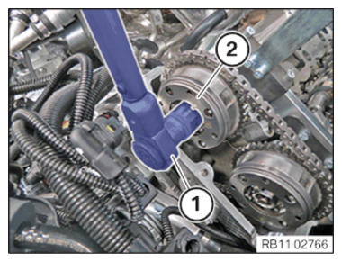
- Tighten the VANOS central valve (1) of the intake side.
TIGHTENING TORQUES SPECIFICATION
| VANOS central valve variable camshaft timing control to camshaft | ||
|---|---|---|
| M22x1 | 2. Joining torque | 30 Nm |
| 3. Joining torque | 50 Nm | |
| 4. Angle of rotation | 30° | |
- (1) Tighten the VANOS central valve of the intake side.
TIGHTENING TORQUES SPECIFICATION
| VANOS central valve variable camshaft timing control to camshaft | ||
|---|---|---|
| M22x1 | 2. Joining torque | 30 Nm |
| 3. Joining torque | 50 Nm | |
| 4. Angle of rotation | 30° | |
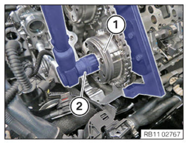
- Install the chain tensioner (2).
Secure screws (1).
TIGHTENING TORQUES SPECIFICATION
| Chain tensioner to cylinder head | ||
|---|---|---|
| M7 | Joining torque | 13 Nm |
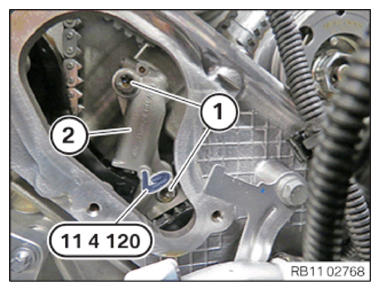
- Remove special tool 0 491 012 (11 4 120) .
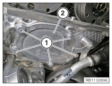
- Position the timing case cover (2).
Tighten the screws (1).
TIGHTENING TORQUES SPECIFICATION
| End cover (oil) to cylinder head | ||
|---|---|---|
| M6x20 | Tightening torque | 10 Nm |
Follow-up work
- Refer to REPLACING THE CYLINDER HEAD COVER GASKET .
- Refer to SCREW CONNECTION OF CYLINDER HEAD COVER, LEFT CYLINDERS 5 TO 8 .
- Refer to CYLINDER HEAD COVER SCREW CONNECTION CYLINDER 5 TO 8 DIFFICULT TO ACCESS .
- Refer to INSTALLING HEAT SHIELD ON THE CYLINDER HEAD COVER CYLINDERS 5 TO 8 .
- Refer to INSTALLING HEAT SHIELD OF THE HIGH PRESSURE PUMP OF CYLINDER HEAD COVER AT LEFT FOR CYLINDERS 5 TO 8 .
- Refer to INSTALLING THE CENTRAL MAGNET .
- Refer to INSTALLING THE LEFT HIGH PRESSURE PUMP .
- Refer to INSTALLING FUEL DELIVERY LINE .
- Refer to PREPARING THE INJECTOR FOR INSTALLATION .
- Refer to INSTALLING INJECTORS .
- Refer to INSTALLING THE SOUND INSULATION ON THE RIGHT-HAND CYLINDER HEAD COVER .
- Refer to SECURING THE WIRING HARNESS ON THE CYLINDER HEAD COVER ON THE RIGHT .
- Refer to INSTALLING ALL IGNITION COILS ON THE RIGHT .
- Refer to BENDING THE HEAT SHIELD TO THE FRONT .
- Refer to RELEASING SCREW BETWEEN THE LEFT AND RIGHT HEAT SHIELD .
- Refer to INSTALLING HEAT SHIELD, TOP .
- Refer to INSTALLING THE LAMBDA OXYGEN SENSOR AND THE MONITORING OXYGEN SENSOR FOR CYLINDERS 1 TO 4 .
- Refer to INSTALLING ENGINE VENTILATION LINE .
- Refer to INSTALLING CENTER BULKHEAD LOWER PART .
- Refer to INSTALLING TENSION STRUT ON SHOCK TOWER .
- Refer to INSTALLING THE CONNECTING SUPPORTS ON THE TUNNEL .
- Refer to IF INSTALLED: INSTALL THE TORSION STRUT ON THE RIGHT, AND ON THE LEFT WHERE REQUIRED .
- Refer to INSTALLING THE RIGHT-HAND CHARGE AIR COOLER .
- Refer to INSTALLING FAN COWL .
- Refer to INSTALLING THE INTEGRATED POWER SUPPLY MODULE (PDM) .
- Refer to INSTALLING RIGHT CLEAN AIR PIPE .
- Refer to CONNECTING THE RIGHT CHARGE AIR LINE TO THE EXHAUST TURBOCHARGER .
- Refer to INSTALLING INTAKE FILTER HOUSING .
- Refer to INSTALLING ACOUSTIC COVER .
- Refer to CHECKING THE COOLANT LEVEL IN THE LOW-TEMPERATURE COOLANT CIRCUIT AND TOP UP, IF NEEDED .
- Refer to INSTALLING BOTH FRONT-END STRUTS .
- Refer to FILLING THE LOW-TEMPERATURE COOLING SYSTEM WITH THE VACUUM FILLING EQUIPMENT .
- Refer to INSTALLING LEFT AND RIGHT WIPER ARM .
- Refer to INSTALLING THE COVER OF THE ENGINE COMPARTMENT ON THE REAR LEFT .
- Refer to INSTALLING THE REAR RIGHT ENGINE COMPARTMENT COVER .