Removing crankshaft
Prerequisite
- Remove and install front axle complete with engine and transmission. Remove and install the engine on the front axle
WARNING:
Working on fuel system.
Risk of fire! Danger of explosion!
Risk of fire! Danger of explosion!
- When working on the fuel system, make sure the workstation has sufficient ventilation, e.g., by means of extraction.
- Tightly seal off open lines and connections; collect any leakage fuel directly at the point of exit.
- No fire, sparks, open flames or smoking.
NOTE:
TECHNICAL INFORMATION
Collect and dispose of emerging fluids. Observe country-specific waste disposal regulations.
Collect and dispose of emerging fluids. Observe country-specific waste disposal regulations.
Preliminary work
- Refer to MOUNTING THE ENGINE TO THE ENGINE SUPPORT BRACKET .
- Refer to RELEASING THE OIL DRAIN PLUG .
- Refer to REMOVING FLYWHEEL .
- Refer to REMOVE DRIVE BELT .
- Refer to REMOVING THE BELT TENSIONER .
- Refer to REMOVING THE VIBRATION DAMPER .
- Refer to REMOVING THE COOLANT PUMP .
- Refer to RELEASING LEFT CHARGE AIR LINE PARTIALLY .
- Refer to PARTIALLY RELEASING THE RIGHT CHARGE AIR LINE .
- Refer to REMOVE THE COOLANT EXPANSION TANK FOR THE LOW-TEMPERATURE COOLANT CIRCUIT (CHARGE COOLER) .
- Refer to REMOVE BOTH CHARGE AIR COOLERS .
- Refer to REMOVE THE CLEAN AIR PIPE OF CYLINDER BANK 1 .
- Refer to REMOVE THE CLEAN AIR PIPE OF CYLINDER BANK 2 .
- Refer to REMOVING THE IGNITION COILS OF CYLINDERS 1 AND 5 .
- Refer to REMOVING FUEL DELIVERY LINE .
- Refer to REMOVING IGNITION COIL OF CYLINDER BANK 2 .
- Refer to REMOVE LEFT HIGH PRESSURE PUMP .
- Refer to REMOVE THE HIGH-PRESSURE RAIL ON THE LEFT .
- Refer to REMOVE THE INJECTORS FOR CYLINDERS 5 TO 8 .
- Refer to REMOVING VANOS SOLENOID ACTUATOR, EXHAUST OF CYLINDER BANK 2 .
- Refer to REMOVING VANOS SOLENOID ACTUATOR, INTAKE OF CYLINDER BANK 2 .
- Refer to REMOVING THE LEFT AND RIGHT EXHAUST TURBOCHARGER .
- Refer to REMOVING FRONT HEAT SHIELD .
- Refer to REMOVING THE OIL FEED LINE AT THE EXHAUST TURBOCHARGER FOR CYLINDERS 5 TO 8 .
- Refer to REMOVE LEFT CYLINDER HEAD COVER .
- Refer to REMOVE THE SEALING CAP ON THE CYLINDER HEAD OF THE CYLINDER BANK 2 .
- Refer to MOVING THE CRANKSHAFT TO THE INSTALLATION POSITION TO ADJUST THE TIMINGS .
- Refer to CHECK THE VANOS ADJUSTER OF CYLINDER BANK 2 .
- Refer to RELAXING CHAIN TENSIONER ON BANK 2 FOR CHECKING OR SETTING TIMING .
- Refer to REMOVING HYDRAULIC CHAIN TENSIONER OF CYLINDER BANK 2 .
- Refer to PRELOADING THE TIMING CHAIN OF CYLINDER BANK 2 .
- Refer to FIXING THE ENGINE IN THE INSTALLATION POSITION ON CYLINDER 1 (SET VALVE TIMINGS) .
- Refer to REMOVING BOTH LEFT VANOS ADJUSTERS .
- Refer to REMOVING SPECIAL TOOL FOR FIXING CAMSHAFTS IN POSITION ON BANK 2 .
- Refer to REMOVING SPECIAL TOOL TO PRETENSION TIMING CHAIN ON CYLINDER BANK 2 .
- Refer to REMOVE LEFT CYLINDER HEAD .
- Refer to REMOVING IGNITION COIL OF CYLINDER BANK 1 .
- Refer to REMOVE RIGHT HIGH-PRESSURE PUMP .
- Refer to REMOVE RIGHT RAIL .
- Refer to REMOVE THE INJECTORS FOR CYLINDERS 1 TO 4 .
- Refer to PARTIALLY RELEASING THE GUIDE TUBE FOR THE OIL DIPSTICK .
- Refer to REMOVING VANOS SOLENOID ACTUATOR, EXHAUST OF CYLINDER BANK 1 .
- Refer to REMOVE THE VANOS SOLENOID ACTUATOR INTAKE OF CYLINDER BANK 1 .
- Refer to REMOVE RIGHT CYLINDER HEAD COVER .
- Refer to REMOVE THE SEALING CAP ON THE CYLINDER HEAD OF THE CYLINDER BANK 1 .
- Refer to CHECKING THE VANOS ADJUSTER OF CYLINDER BANK 1 .
- Refer to RELIEVING THE CHAIN TENSIONER AT CYLINDER BANK 1 FOR CHECKING OR SETTING THE VALVE TIMINGS .
- Refer to REMOVING HYDRAULIC CHAIN TENSIONER OF CYLINDER BANK 1 .
- Refer to PRELOADING THE TIMING CHAIN OF CYLINDER BANK 1 .
- Refer to FIXING THE ENGINE IN THE INSTALLATION POSITION ON CYLINDER 1 (SET VALVE TIMINGS) .
- Refer to REMOVING BOTH RIGHT VANOS ADJUSTERS .
- Refer to REMOVING SPECIAL TOOL FOR FIXING CAMSHAFTS ON BANK 1 .
- Refer to REMOVING THE SPECIAL TOOL TO PRETENSION THE TIMING CHAIN AT CYLINDER BANK 1 .
- Refer to REMOVE RIGHT CYLINDER HEAD .
- Refer to REMOVE LOWER OIL PAN SECTION .
- Refer to REMOVE OIL PUMP .
- Refer to REMOVE FRONT AXLE DIFFERENTIAL .
- Refer to REMOVING UPPER OIL SUMP SECTION, ENGINE REMOVED .
- Refer to REMOVING THE PISTON WITH CONNECTING ROD .
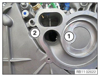
Removing sealing cap with radial shaft seal (oil pan removed)
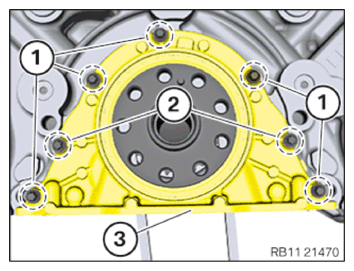
- Loosen screws (1).
- Loosen screws (2).
- Remove the sealing cap with radial shaft seal (3).
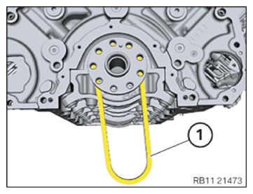
- Remove the roller chain (1).
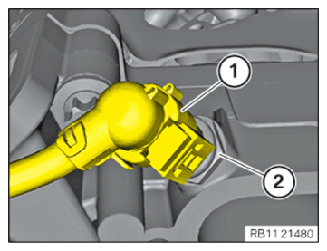
- Unlock and disconnect the plug connection (1) on the coolant temperature sensor (2).
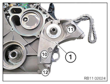
Unscrew the screw connection 1 on the timing case cover in front
- Loosen screws in the order (10) to (12).
- Remove the carrier plate (1).
Release the screw connection 2 on the front timing case cover
- Loosen screws in the order (9) to (3).
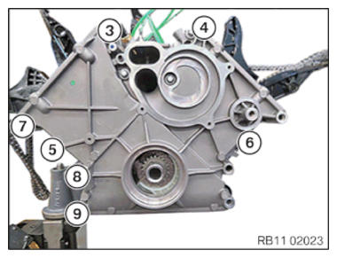
Release the screw connection 3 on the timing case cover in front
- Loosen screws in the order (1) to (2).
- Remove timing case cover.
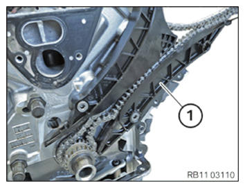
- Remove the slide rail (1).
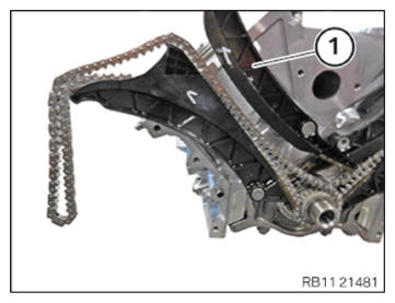
Remove the tensioning rail of the timing chain for cylinder 1-4
- Remove the tensioning rail (1) with the timing chain (2) from the crankshaft gearing.
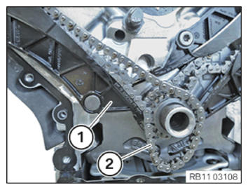
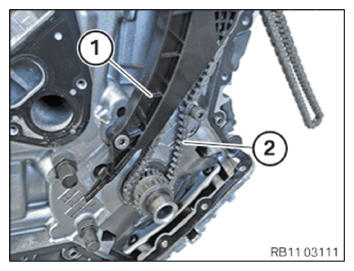
Removing the slide rail of the timing chain for cylinders 5 to 8
- Remove the slide rail (1).
Remove the tensioning rail of the timing chain for cylinder 5-8
- Remove the tensioning rail (1) with the timing chain (2) from the crankshaft gearing.
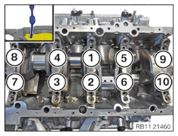
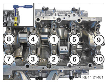
- Observe the arrangement of the main bearing cap as well as the assignment of the crankshaft bearing caps from (1) to (5).
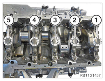
- Loosen the main bearing transverse screws on the spacer bolts (1), the screws (2), and the spacer screw (3).
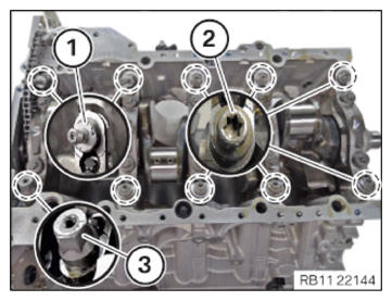
- Unscrew all threaded bushing sleeves (1).
NOTE:
The operations shown only for one side must be carried out on both sides.
- Loosen screws (1).
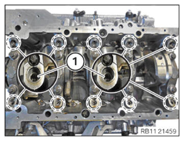
- Release the collar screws (M8) in the sequence (10) to (1).
- Release the collar screws (M11) in the sequence (10) to (1).
- Remove the main bearing cap.
CAUTION:
Component with heavy weight. Injury hazard!
- Note component's center of gravity.
- Support component using a jack.
- Secure component against falling off the jack.
NOTE:
TECHNICAL INFORMATION
The work must be performed with vehicle care to prevent component damage.
The work must be performed with vehicle care to prevent component damage.
- Remove the crankshaft with a support person (weight approx. 25 kg).
- Lift out crankshaft and set down safely (secure against turning).