Replacing the main bearing shells and the guide bearing shells
NOTE:
RISK OF DAMAGE
Engine damage caused by incorrectly installed bearing shells and bearing brackets.
If the bearing shells and bearing brackets are installed incorrectly, then engine damage can occur.
Engine damage caused by incorrectly installed bearing shells and bearing brackets.
If the bearing shells and bearing brackets are installed incorrectly, then engine damage can occur.
- Always install all bearing shells and bearing brackets in the same position from which they were removed.
NOTE:
TECHNICAL INFORMATION
The main bearing shells and guide bearing shells are classified by numbers.
Observe the classification of the main and guide bearing shells.
The main bearing shells and guide bearing shells are classified by numbers.
Observe the classification of the main and guide bearing shells.
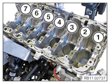
- Remove the main bearing shells with lubricating groove (1) to (3) and (5) to (7) from the crankcase.
- Remove the guide bearing shell with lubricating groove (4) from the crankcase.
- Remove the main bearing shells (1) to (3) and (5) to (7) from the crankshaft bearing caps.
- Remove the guide bearing shell (4) from the crankshaft bearing cap.
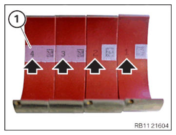
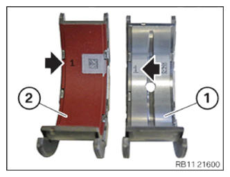
- Make sure that the correct classification (arrows) is installed.
- Replace main bearing shells (1) with
lubricating groove.
Parts: Main bearing shells with lubricating groove
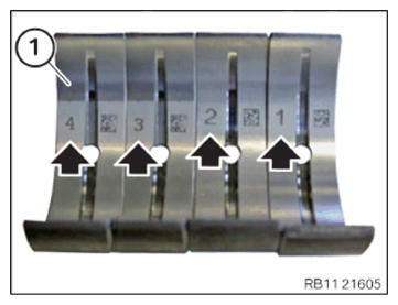
- Make sure that the correct classification (arrows) is installed.
- Replace main bearing shells (1) without
lubricating groove.
Parts: Main bearing shells without lubricating groove
- Make sure that the correct classification (arrows) is installed.
- Replace the guide bearing shell with lubricating groove (1) and the guide bearing shell (2) without lubricating groove.
Parts: Guide bearing shells
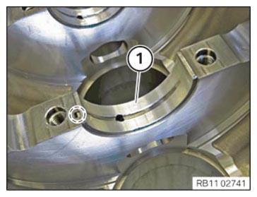
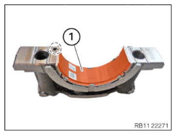
- Make sure the crankshaft main bearing shell (1) is correctly installed with the guide lug in the highlighted
area.
- Make sure the crankshaft guide shell (1) is correctly installed with the guide lug in the highlighted
area.
- Make sure the crankshaft main bearing shell (1) is correctly installed with the guide lug in the highlighted area.
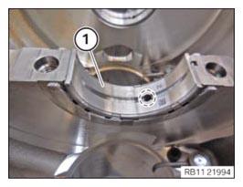
- Make sure the crankshaft guide shell (1) is correctly installed with the guide lug in the highlighted
area.
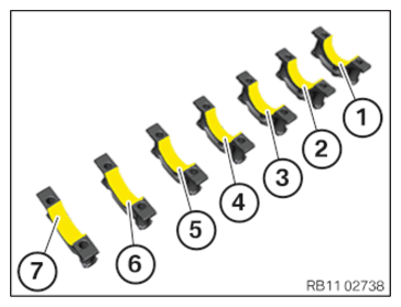
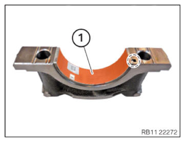
- Install the main bearing shells (1) to (3) and (5) to (7) in the crankshaft bearing cap.
- Install the guide bearing shell (4) in the crankshaft bearing cap.
- Oil all main bearing shells and guide bearing shells (1) to (7).
- Install main bearing shells with lubricating groove (1) to (3) and (5) to (7) in the crankcase.
- Install the guide bearing shell with lubricating groove (4) in the crankcase.
- Oil all main bearing shells and guide bearing shells with lubricating groove (1) to (7).
Follow-up work
- Refer to INSTALLING THE CRANKSHAFT .
- Refer to CHECK THE COEFFICIENT OF FRICTION FOR THE CRANKSHAFT .
- Refer to CHECKING THE CRANKSHAFT SIDE CLEARANCE .
- Refer to MEASURING ALL PISTONS .
- Refer to MEASURING A CYLINDER .
- Refer to INSTALLING ALL PISTONS WITH CONNECTING ROD .
- Refer to INSTALL THE OIL VACUUM PUMP .
- Refer to INSTALLING TIMING CHAIN .
- Refer to INSTALLING THE REAR TIMING CASE COVER .
- Refer to INSTALLING THE OIL DEFLECTOR
- Refer to REFITTING ENGINE OIL PAN .
- Refer to INSTALLING THE FLYWHEEL .
- Refer to REPLACING FRONT CRANKSHAFT SEAL .
- Refer to INSTALLING THE VIBRATION DAMPER .
- Refer to INSTALLING THE DRIVE BELT FOR THE STARTER MOTOR GENERATOR .
- Refer to INSTALLING STARTER MOTOR
- Refer to INSTALL THE ACOUSTIC COVER FOR THE OIL SUMP .
- Refer to SEAL THE OIL DUCT .
- Refer to CLEAN SEALING SURFACES .
- Refer to INSTALLING THE CYLINDER HEAD GASKET .
- Refer to BLOCKING THE CRANKSHAFT IN THE TDC FIRING POSITION OF CYLINDER 1 .
- Refer to INSTALLING THE CYLINDER HEAD .
- Refer to ADJUSTING THE CAMSHAFTS WITH THE SPECIAL TOOL .
- Refer to INSTALLING THE INTAKE ADJUSTER .
- Refer to INSTALLING THE VANOS CENTRAL VALVE OF THE INTAKE ADJUSTER .
- Refer to INSTALL EXHAUST CAMSHAFT ADJUSTER .
- Refer to INSTALLING THE VANOS CENTRAL VALVE OF THE EXHAUST CAMSHAFT ADJUSTER .
- Refer to PRE-TENSIONING THE TIMING CHAIN WITH THE SPECIAL TOOL .
- Refer to TIGHTENING THE VANOS CENTRAL VALVE OF THE EXHAUST CAMSHAFT ADJUSTER .
- Refer to TIGHTENING THE VANOS CENTRAL VALVE OF THE INTAKE ADJUSTER .
- Refer to DISASSEMBLING ALL SPECIAL TOOLS
- Refer to INSTALL CHAIN TENSIONER .
- Refer to CHECKING THE TIMINGS OF THE CAMSHAFT .
- Refer to INSTALLING THE COOLANT LINE BETWEEN THE CYLINDER HEAD AND THE COOLANT PUMP .
- Refer to INSTALLING THE OIL RETURN LINE FOR THE EXHAUST TURBOCHARGER .
- Refer to INSTALLING CYLINDER HEAD COVER .
- Refer to INSTALLING BOTH ACTUATORS .
- Refer to PREPARE THE INJECTORS FOR INSTALLATION .
- Refer to INSTALLING THE HIGH-PRESSURE RAIL WITH INJECTORS OF THE CYLINDERS 4 TO 6 .
- Refer to INSTALLING RAIL WITH INJECTORS OF CYLINDERS 1 TO 3 .
- Refer to INSTALLING THE HIGH-PRESSURE LINE BETWEEN THE HIGH-PRESSURE PUMP AND THE HIGH-PRESSURE RAIL .
- Refer to INSTALLING HIGH PRESSURE PUMP .
- Refer to INSTALLING FUEL DELIVERY LINE .
- Refer to REPLACE SPARK PLUGS (540i 2017-2020) , or INSTALLING ALL SPARK PLUGS (540i 2021-2022) .
- Refer to INSTALL ALL IGNITION COILS .
- Refer to INSTALL CATALYTIC CONVERTER .
- Refer to INSTALLING THE OXYGEN SENSOR MONITOR .
- Refer to INSTALLING LAMBDA OXYGEN SENSOR .
- Refer to INSTALLING THE INTAKE PLENUM .
- Refer to INSTALLING THE TANK VENT VALVE .
- Refer to INSTALLING ACOUSTIC COVER AT REAR .
- Refer to TOPPING UP THE MOTOR OIL .
- Refer to RELEASING THE OIL FILTER COVER (540i 2017-2020) , or REMOVING THE OIL FILLER CAP (540i 2021-2022) .
- Refer to REMOVING THE ENGINE FROM THE ASSEMBLY JIG .
- Refer to MOUNTING THE ENGINE ON THE FRONT AXLE .
- Refer to INSTALLING THE COMPLETE FRONT AXLE INCLUDING ENGINE AND TRANSMISSION .