Install engine
Further information is available.
WARNING:
Vehicle may slip off the vehicle hoist if the vehicle hoist is handled incorrectly.
Danger! Immobilization period-threatening injuries!
Danger! Immobilization period-threatening injuries!
- Observe safety instructions on raising the vehicle using a vehicle hoist.
- For additional information see: 00... RAISE THE VEHICLE USING A VEHICLE LIFT .
WARNING:
Car may slip off the vehicle hoist if the weight is distributed unevenly.
Danger! Immobilization period-threatening injuries!
Danger! Immobilization period-threatening injuries!
- Ensure there is a specific weight compensation on the car.
CAUTION:
Heavy component.
Heavy components can lead to injury or damage.
Heavy components can lead to injury or damage.
- Remove and install heavy components with the aid of another person/other persons.
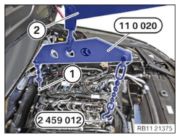
- Insert and install the engine with the special tool 2 220 718 (2).
- Lower the engine with the special tool 2 220 718 (2).
- Feed out the special tool 0 490 567 (11 0 020) at the special tool 2 220 718 (2).
- Guide out special tool 0 490 567 (11 0 020) on engine mounting bracket (1).
- Guide out special tool 0 490 567 (11 0 020) on special tool 2 459 012.
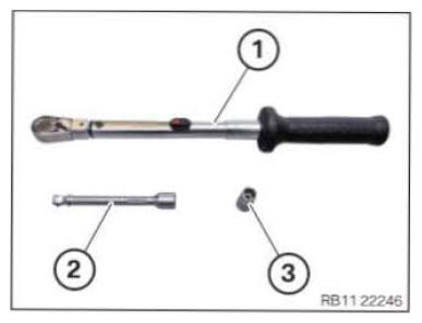
- Keep all the standard tools ready.
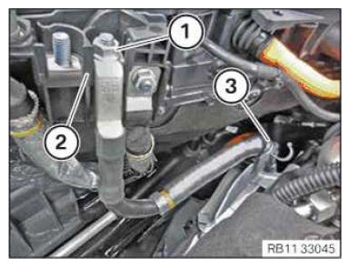
Number Description 1 Standard torque wrench 2 Swivelling extension 3 External Torx E14 - Position suitable tool (1).
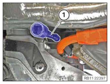
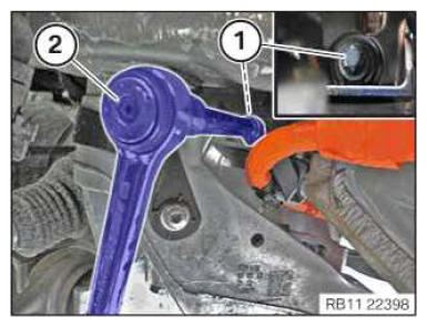
- Tighten bolt (1) of the left engine mount using a standard tool (2) sideways.TIGHTENING TORQUES SPECIFICATION
Engine mount to engine support bracket M12 tightening torque
100 Nm - Tighten the bolt (1) of the right engine mount using a standard tool from the top.TIGHTENING TORQUES SPECIFICATION
Engine mount to engine support bracket M12 tightening torque
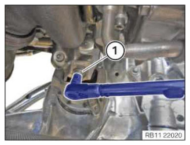
100 Nm - Connect and lock the transmission oil lines (1) and (2).
- Ensure that transmission oil lines (1) and (2) engage audibly.
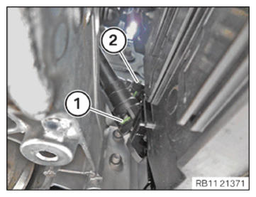
- Tighten the bolts (1) on the front subframe (2).TIGHTENING TORQUES SPECIFICATION
Holder for transmission oil lines to front subframe M6 tightening torque
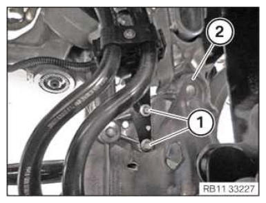
12 Nm - Guide in and position manifold support (2).
- Tighten down screw (1).TIGHTENING TORQUES SPECIFICATION
Manifold bracket to crankcase M6x16 tightening torque
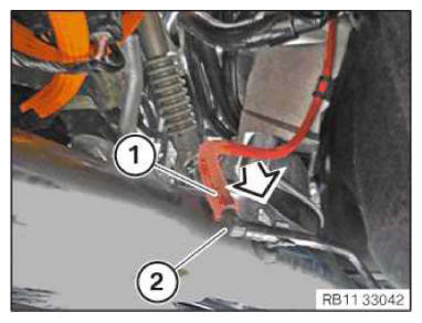
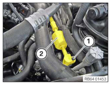
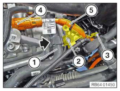
8 Nm - Connect the vacuum hose (1) with the vacuum line (2) in arrow direction.
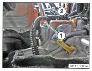
- Insert and position the positive battery cable (2).
- Tighten nut (1).TIGHTENING TORQUES SPECIFICATION
Positive battery cable Positive pole screw tightening torque
15 Nm - Secure positive battery cable (2) at the clamp (3).
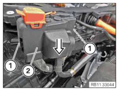
- Thread in cover (2) downwards in arrow direction.
The cover (2) must engage audibly in the detents (1).
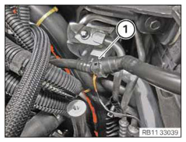
- Connect tank went line (4) and lock.
The tank vent line (4) must engage audibly.
- Connect and lock fuel simply line (3).
The lock (2) must engage audibly.
- Feed In and install the clamp (1).
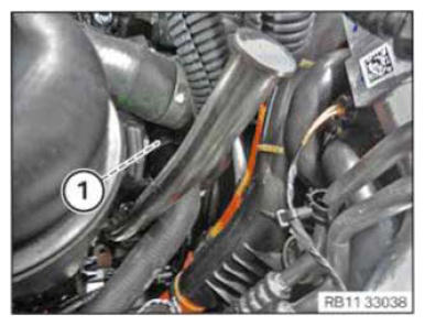
- Connect the vacuum line (1) and lock.
The vacuum line (1) must audibly engage.
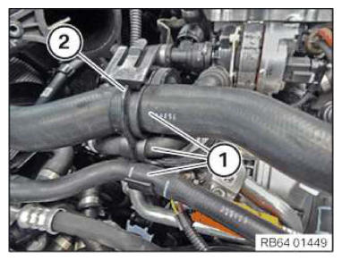
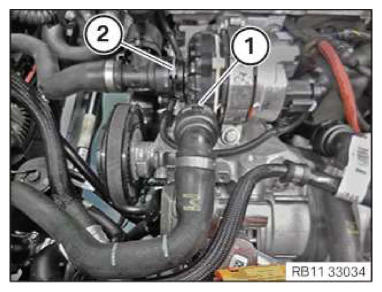
- Connect and lock the coolant lines (1).
The coolant lines (1) must engage audibly.
- Replace O-rings.
Parts: O-rings.
- Feed in pressure line (2) between the air conditioning condenser and the air conditioning compressor and fix it to the air conditioning condenser.
- Tighten down screw (1).TIGHTENING TORQUES SPECIFICATION
Refrigerant lines to air conditioning condenser/connecting piece M6 Tightening torque
13 Nm - Replace O-rings.
Parts: O-rings.
- Feed in and install the refrigerant line (4).
- Tighten down screw (3).TIGHTENING TORQUES SPECIFICATION
Refrigerant line on air conditioning compressor M8 tightening torque
19 Nm - Feed in and install the refrigerant line (2).
- Tighten down screw (1).TIGHTENING TORQUES SPECIFICATION
Refrigerant line on air conditioning compressor M8 tightening torque
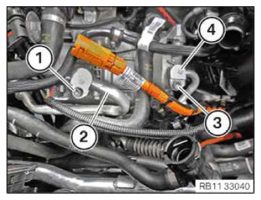
19 Nm - Replace screws (2) and (3).
Parts: screws.
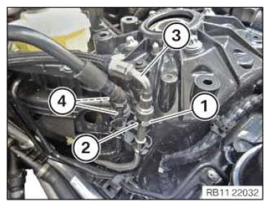
- Position high-voltage cable (5) and connect and lock the connector (4).
- Tighten down screw (3).TIGHTENING TORQUES SPECIFICATION
Holder for oil filter housing Torx screw M6x16
Replace screw.tightening torque
4.0 Nm - Tighten down screw (2).TIGHTENING TORQUES SPECIFICATION
Holder for air conditioning compressor Hexagon screw
M6x16
Replace screw.tightening torque
8 Nm - Insert the coolant hose (1) in the holder (arrow) and close the holder (arrow).
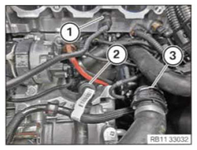
- Connect and lock the coolant lines (1), (2) and (3).
Coolant lines (1), (2) and (3) must engage audibly.
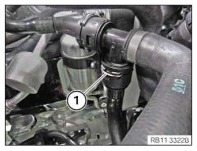
- Connect and lock coolant line (1).
The coolant line (1) must audibly engage.
- Install holder (2).
- Insert the coolant hoses (1) In the holder (2).
- Connect and lock coolant lines (1) and (2).
The coolant lines (1) and (2) must audibly engage.
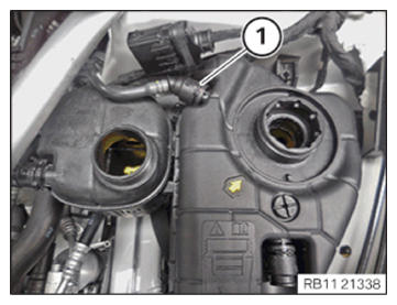
- Feed in coolant line (1) and position.
The coolant line (1) must engage audibly.
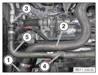
- Insert the coolant line (5) and install it.
The lock (3) must engage audibly.
- Insert and install the coolant fine (5) in the damp (4).
- Lock clamp (4).
- Connect and lock coolant line (2).
The lock (1) must engage audibly.
Follow-up work:
- Refer to REMOVING SPECIAL TOOL FROM THE CYLINDER HEAD .
- Refer to INSTALLING THE INTAKE PLENUM (2018-2020) or INSTALLING THE INTAKE PLENUM (2021-2022) .
- Refer to INSTALLING THE TANK VENT VALVE (2018-2020) or INSTALLING THE TANK VENT VALVE (2021-2022) .
- Refer to INSTALLING CONTROL UNIT BRACKET (2018-2020) or INSTALLING CONTROL UNIT BRACKET (2021-2022) .
- Refer to INSTALLING THE INTEGRATED POWER SUPPLY MODULE (PDM) (2018-2020) or INSTALLING THE INTEGRATED POWER SUPPLY MODULE (PDM) (2021-2022) .
- Refer to INSTALLING THE DME CONTROL UNIT (2018-2020) or INSTALLING THE DME CONTROL UNIT (2021-2022) .
- Refer to INSTALLING FUEL DELIVERY LINE (2018-2020) or INSTALLING FUEL DELIVERY LINE (2021-2022) .
- Refer to INSTALLING THE IGNITION COILS (2018-2020) or INSTALLING ALL IGNITION COILS (2021-2022) .
- Refer to CONNECTING THE COOLANT LINES FOR THE HIGH-TEMPERATURE COOLANT CIRCUIT .
- Refer to CONNECTING THE COOLANT LINE OF LOW-TEMPERATURE COOLANT CIRCUIT .
- Refer to REMOVING THE DRIVE BELT FOR COOLANT PUMP (2018-2020) or REMOVING THE DRIVE BELT FOR COOLANT PUMP (2021-2022) .
- Refer to INSTALLING THE ACOUSTIC COVER FOR THE ENGINE AT THE FRONT (2018-2020) or INSTALLING THE ACOUSTIC COVER FOR THE ENGINE AT THE FRONT (2021-2022) .
- Refer to INSTALLING AUTOMATIC TRANSMISSION (GA8HP75HZ) .
- Refer to FASTENING THE PROP SHAFT (PARTIALLY REMOVED)
- Refer to INSTALLING TRANSMISSION CROSS MEMBER .
- Refer to INSTALLING THE HEAT SHIELDS .
- Refer to INSTALLING CATALYTIC CONVERTER (2018-2020) or INSTALLING CATALYTIC CONVERTER (2021-2022) .
- Refer to INSTALLING THE COMPLETE EXHAUST SYSTEM .
- Refer to INSTALLING THE CONNECTING SUPPORTS ON THE TUNNEL .
- Refer to IF INSTALLED: INSTALLING THE TORSION STRUT ON THE RIGHT, AND ON THE LEFT WHERE REQUIRED .
- Refer to INSTALLING THE REAR AXLE COVER .
- Refer to INSTALLING LAMBDA OXYGEN SENSOR (2018-2020) or INSTALLING LAMBDA OXYGEN SENSOR (2021-2022) .
- Refer to INSTALLING CLEAN AIR PIPE (2018-2020) or INSTALLING CLEAN AIR PIPE (2021-2022) ..
- Refer to INSTALLING CHARGE AIR LINE (2018-2020) or INSTALLING CHARGE AIR LINE (2021-2022) .
- Refer to INSTALLING RESONATOR .
- Refer to INSTALLING CENTER BULKHEAD LOWER PART
- Refer to INSTALLING LEFT SEALING FRAME .
- Refer to INSTALLING ACOUSTIC COVER AT REAR
- Refer to FASTENING HIGH-VOLTAGE CABLES ON THE ELECTRICAL MACHINE ELECTRONICS .
- Refer to INSTALLING THE CENTER COWL UPPER PART
- Refer to INSTALLING TENSION STRUT ON SHOCK TOWER .
- Refer to INSTALLING WINDSHIELD PANEL COVER .
- Refer to INSTALLING LEFT AND RIGHT WIPER ARM .
- Refer to INSTALLING THE REAR RIGHT ENGINE COMPARTMENT COVER .
- Refer to INSTALLING THE COVER OF THE ENGINE COMPARTMENT ON THE REAR LEFT .
- Refer to INSTALLING THE FRONT HOOD SEAL AT THE REAR .
- Refer to EVACUATE AND CHARGE CONDITIONING .
- Refer to CONNECTING ALL BATTERY GROUND LEADS .
- Refer to FILLING AND VENTING THE COOLANT CIRCUIT .
- Refer to FILLING AND VENTING THE LOW-TEMPERATURE COOLANT CIRCUIT .
- Refer to CHECKING/TOPPING UP THE OIL LEVEL IN THE AUTOMATIC TRANSMISSION .
- Refer to CHECK ENGINE OIL LEVEL .
- Refer to INSTALLING BOTH FRONT-END STRUTS
- Refer to INSTALLING THE COVER ON THE LEFT AND RIGHT IN THE ENGINE COMPARTMENT AT THE TOP
- Refer to INSTALLING THE REAR SECTION OF THE FRONT WHEEL ARCH COVER ON THE LEFT AND RIGHT .
- Refer to INSTALLING THE COVER OF THE STEERING ASSEMBLY ON THE LEFT AND RIGHT .
- Refer to INSTALLING THE FRONT LEFT AND RIGHT WHEELS .
- Refer to INSTALLING THE REAR THRUST FIELD .
- Refer to INSTALLING REAR UNDERBODY PROTECTION .
- Refer to INSTALLING THE UNDERBODY PROTECTION OF THE STEERING GEAR OR THE FRONT THRUST FIELD .
- Refer to INSTALLING THE FRONT UNDERBODY PROTECTION OR FRONT THRUST FIELD (STIFFENING PLATE) .
- Refer to INSTALLING THE ACOUSTIC COVER (2018-2020) or INSTALLING THE ACOUSTIC COVER (2021-2022) .
- Refer to TAKING HOOD OUT OF THE SERVICE POSITION .