Checking camshaft timing
NOTE:
DANGER
High-voltage system.
The high-voltage system operates on the basis of hazardous, electrical voltage and high currents. Danger to life through electric shock!
High-voltage system.
The high-voltage system operates on the basis of hazardous, electrical voltage and high currents. Danger to life through electric shock!
- All work on the high-voltage system may only be carried out by specially trained and technically experienced personnel.
- For additional information see:
- For additional information see:
WARNING:
Hot surfaces.
Risk of burning!
Risk of burning!
- Perform all work only on components that have cooled down.
WARNING:
Working on fuel system.
Risk of fire! Danger of explosion!
Risk of fire! Danger of explosion!
- When working on the fuel system, make sure that the workbay is sufficiently ventilated, e.g. using extraction unit.
- Tightly seal off open lines and connections; collect any escaping fuel directly at the point of exit.
- No fire, sparks, open flames or smoking.
CAUTION:
On releasing high pressure line, fuel may emerge at high speed.
Danger of injury!
Danger of injury!
- Wear suitable personal protective equipment.
- Allow the cooling system to cool down to a temperature below 40°C before starting installation work.
- Note warnings on cylinder head cover.
NOTE:
TECHNICAL INFORMATION
Collect and dispose of emerging fluids. Observe country-specific waste disposal regulations.
Collect and dispose of emerging fluids. Observe country-specific waste disposal regulations.
Preliminary works
- Refer to BRINGING FRONT COMPARTMENT LID IN THE SERVICE POSITION .
- Refer to REMOVING THE ACOUSTIC COVER .
- Refer to REMOVING THE SEAL FOR THE REAR BONNET .
- Refer to REMOVING THE COVER OF THE ENGINE COMPARTMENT AT THE REAR LEFT .
- Refer to REMOVING LEFT AND RIGHT WIPER ARM .
- Refer to REMOVING COWL PANEL COVER .
- Refer to REMOVING TRAILING LINK AT SPRING BOLT .
- Refer to REMOVING THE CENTER BULKHEAD UPPER PART .
- Refer to REMOVING THE RIGHT SEALING FRAME .
- Refer to LOOSENING HIGH-VOLTAGE CABLES ON THE ELECTRICAL MACHINE ELECTRONICS .
- Refer to REMOVING ACOUSTIC COVER AT REAR .
- Refer to REMOVING LEFT SEALING FRAME .
- Refer to REMOVING THE CENTER BULKHEAD LOWER SECTION .
- Refer to REMOVING INTAKE SILENCER HOUSING .
- Refer to REMOVING RESONATOR .
- Refer to REMOVING CLEAN AIR PIPE .
- Refer to REMOVING CHARGE AIR LINE .
- Refer to REMOVING THE CYLINDER HEAD COVER ACOUSTIC COVER .
- Refer to REMOVING IGNITION COILS .
- Refer to REMOVING ALL SPARK PLUGS .
- Refer to REMOVING THE HIGH PRESSURE LINE BETWEEN THE HIGH PRESSURE PUMP AND THE RAIL .
- Refer to REMOVING FUEL DELIVERY LINE .
- Refer to REMOVING HIGH PRESSURE PUMP .
- Refer to REMOVING INJECTORS .
- Refer to REMOVING THE FRONT UNDERBODY PROTECTION OR FRONT THRUST FIELD .
- Refer to REMOVING THE UNDERBODY PROTECTION OF THE STEERING GEAR AND FRONT STIFFENING PLATE RESPECTIVELY .
- Refer to REMOVING REAR STIFFENING PLATE .
- Refer to DRAINING THE COOLANT FROM THE HIGH-TEMPERATURE COOLING SYSTEM .
- Refer to REMOVING THE ACOUSTIC COVER FOR THE ENGINE AT THE FRONT .
- Refer to REMOVING AUXILIARY COOLANT PUMP FOR THE EXHAUST TURBOCHARGER .
- Refer to REMOVING FRONT ENGINE ENCAPSULATION .
- Refer to REMOVING BOTH ACTUATORS .
- Refer to REMOVING THE CYLINDER HEAD COVER .
- Refer to PARTIALLY RELEASING ACOUSTIC COVER OF OIL SUMP .
- Refer to REMOVING THE THERMOSTAT FROM THE TRANSMISSION OIL LINES .
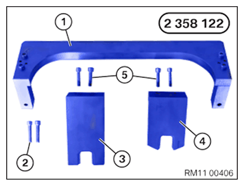
- Have the special tool 2 358 122
ready.
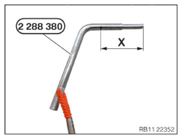
Number Description 1 Basic carrier 2 Basic carrier screws on cylinder head 3 Gauge to fix exhaust camshaft 4 Gauge to fix intake camshaft 5 Screw gauge on basic carrier - Have the special tool 2 288 380
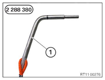
ready.
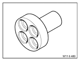
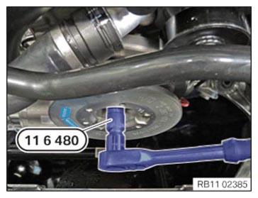
Number Description 1 Locating stud - Have the special tool 0 493 380 (11 6 480)
ready.
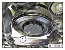
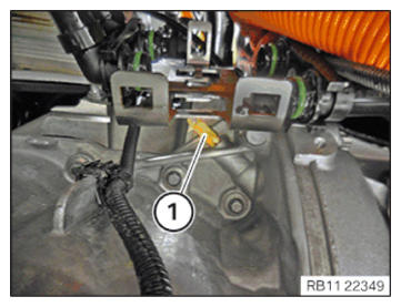
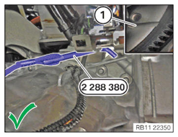
- If applicable, remove the cover (1).NOTE: RISK OF DAMAGE
Damage to the engine.
The engine may be damaged if it is manually rotated in the wrong direction.- Turn the combustion engine exclusively by hand in the correct direction of rotation: a) Clockwise, facing the vibration damper or b) Counter-clockwise, facing the chain drive, (b) only applies when the rear timing chain is installed.
- Turn the engine with the special tool 0 493 380 (11 6 480) to the TDC firing position of cylinder (1).
- Thread the sealing cap (1) out and remove.
- Make sure that special tool 2 288 380
is inserted in the dowel hole up to dimension (X).
Dimension (X) = 55 mm
- Check whether the correct dimension has been achieved.
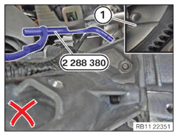
The special tool 2 288 380 is incorrectly positioned.
The TDC firing position (1) of cylinder 1 was not reached.
- Check whether the correct dimension has been achieved,
The special tool 2 288 380 is correctly positioned.
The engine is in the TDC firing position (1) of the 1 st cylinder.
Check
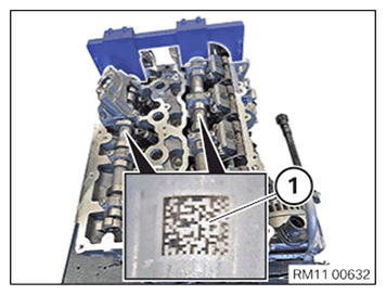
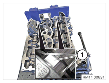
- Check if the marks (1) for the intake and exhaust camshaft can be read from the top.
Result
» Marks (1) cannot be read from the top.
Measure
- Turn the camshafts to the correct position or readjust the timing.
Check
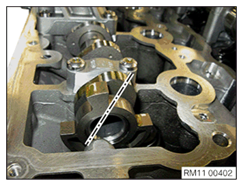
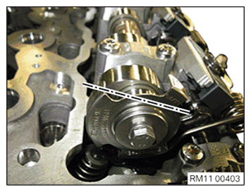
- Check whether the middle one of the 3 flattened areas (1) on both camshafts points upwards. The special tool 2 358 122 can also be mounted when the camshafts are twisted by 180° (center flattened area points downwards).
Result
» The middle one of the 3 flattened areas (1) does not point upwards.
Measure
- Turn the camshafts to the correct position so that the middle one of the 3 flattened areas (1) on both camshafts points upwards.
- The cam on the exhaust camshaft on the first cylinder points obliquely inwards to the right.
- The cam on the intake camshaft on the first cylinder points obliquely to the left.
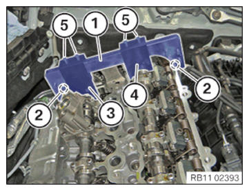
- Secure the basic carrier (1) of the special tool 2 358 122 with the screws (2) on the cylinder head.
- Position gauge (3) with the recess on the exhaust camshaft and fix with the screws (5) on the basic carrier (1).
- Position gauge (4) with the recess on the intake camshaft and fix with the screws (5) on the basic carrier (1).NOTE: If special tool 2 358122 cannot be mounted, the timing must be readjusted.
Follow-up Work
- Refer to INSTALLING THE THERMOSTAT ON THE TRANSMISSION OIL LINES .
- Refer to SECURING THE OIL SUMP ACOUSTIC COVER .
- Refer to INSTALLING CYLINDER HEAD COVER .
- Refer to INSTALLING BOTH ACTUATORS .
- Refer to PREPARING THE INJECTORS FOR INSTALLATION .
- Refer to INSTALLING INJECTORS .
- Refer to PREPARING FOR THE INSTALLATION OF THE HIGH PRESSURE PUMP .
- Refer to INSTALLING HIGH PRESSURE PUMP .
- Refer to INSTALLING FUEL DELIVERY LINE .
- Refer to INSTALLING THE HIGH-PRESSURE LINE BETWEEN THE HIGH-PRESSURE PUMP AND THE HIGH-PRESSURE RAIL .
- Refer to INSTALLING ALL SPARK PLUGS .
- Refer to INSTALLING THE IGNITION COILS .
- Refer to INSTALLING CENTER BULKHEAD LOWER SECTION .
- Refer to INSTALLING ACOUSTIC COVER AT REAR .
- Refer to FASTENING HIGH-VOLTAGE CABLES ON THE ELECTRICAL MACHINE ELECTRONICS .
- Refer to INSTALLING RIGHT SEALING FRAME .
- Refer to INSTALLING LEFT SEALING FRAME .
- Refer to INSTALLING THE CENTER BULKHEAD UPPER PART .
- Refer to INSTALLING TENSION STRUT ON SHOCK TOWER .
- Refer to INSTALLING COWL PANEL COVER .
- Refer to INSTALLING LEFT AND RIGHT WIPER ARM .
- Refer to INSTALLING THE COVER OF THE ENGINE COMPARTMENT ON THE REAR LEFT .
- Refer to INSTALLING THE SEAL FOR THE BONNET .
- Refer to INSTALLING FRONT ENGINE ENCAPSULATION .
- Refer to INSTALLING AUXILIARY COOLANT PUMP FOR THE EXHAUST TURBOCHARGER .
- Refer to INSTALLING THE ACOUSTIC COVER FOR THE ENGINE AT THE FRONT .
- Refer to CONNECTING THE COOLANT LINE OF HIGH-TEMPERATURE COOLANT CIRCUIT .
- Refer to INSTALLING CHARGE AIR LINE .
- Refer to INSTALLING CLEAN AIR PIPE .
- Refer to INSTALLING RESONATOR .
- Refer to INSTALLING THE CYLINDER HEAD COVER ACOUSTIC COVER .
- Refer to INSTALLING INTAKE SILENCER HOUSING .
- Refer to FILLING THE HIGH-TEMPERATURE COOLING SYSTEM WITH THE VACUUM FILLER DEVICE .
- Refer to BLEEDING THE HIGH-TEMPERATURE COOLANT CIRCUIT .
- Refer to CHECKING/TOPPING UP OIL LEVEL IN AUTOMATIC TRANSMISSION .
- Refer to INSTALLING ACOUSTIC COVER .
- Refer to INSTALLING THE REAR STIFFENING PLATE .
- Refer to INSTALLING THE UNDERBODY PROTECTION OF THE STEERING GEAR OR THE FRONT STIFFENING PLATE .
- Refer to INSTALLING THE FRONT UNDERBODY PROTECTION OR FRONT THRUST FIELD .
- Refer to TAKING BONNET OUT OF THE SERVICE POSITION .