Removing valve springs
WARNING:
Hot fluids.
Risk of scalding!
Risk of scalding!
- Conduct all work in the vehicle wearing appropriate personal protective equipment only.
WARNING:
Hot surfaces.
Risk of burning!
Risk of burning!
- Perform all work only on components that have cooled down.
CAUTION:
On releasing high pressure line, fuel may emerge at high speed.
Injury hazard!
Injury hazard!
- Wear suitable personal protective equipment.
- Before performing any installation work, allow cooling system to cool down to less than 40°C.
- Note warnings on cylinder head cover.
NOTE:
TECHNICAL INFORMATION
Collect and dispose of emerging fluids. Observe country-specific waste disposal regulations.
Collect and dispose of emerging fluids. Observe country-specific waste disposal regulations.
Preliminary work
- Refer to DISCONNECTING ALL BATTERY GROUND LEADS .
- Refer to DRAINING THE MOTOR OIL .
- Refer to REMOVING INTAKE SILENCER HOUSING .
- Refer to REMOVING THE RESONATOR WITH THE TOP CLEAN AIR PIPE .
- Refer to REMOVING BOTTOM CLEAN AIR PIPE .
- Refer to REMOVING THE COVER ON LEFT AND RIGHT IN THE ENGINE COMPARTMENT AT THE TOP .
- Refer to REMOVING THE LEFT AND RIGHT FRONT-END STRUT .
- Refer to REMOVING FRONT CROSS CONNECTION .
- Refer to REMOVING THE REAR TOP CROSS CONNECTION .
- Refer to REMOVING THE FAN COWL .
- Refer to REMOVING CHARGE AIR LINE .
- Refer to REMOVING THE SEAL FOR THE HOOD REAR .
- Refer to REMOVING ACOUSTIC COVER AT REAR .
- Refer to REMOVING THE COVER OF THE ENGINE COMPARTMENT AT THE REAR LEFT .
- Refer to REMOVING LEFT AND RIGHT WIPER ARM .
- Refer to REMOVING THE COWL COVER .
- Refer to REMOVING TRAILING LINK AT SPRING BOLT .
- Refer to REMOVING THE COWL UPPER PART IN THE CENTER .
- Refer to REMOVING THE SEALING FRAME ON LEFT AND RIGHT .
- Refer to REMOVING THE CENTER BULKHEAD LOWER PART .
- Refer to REMOVING BOTH ACTUATORS .
- Refer to REMOVING FRONT ENGINE ENCAPSULATION .
- Refer to REMOVING IGNITION COILS .
- Refer to REMOVING THE HIGH PRESSURE LINE BETWEEN THE RAIL AND THE HIGH PRESSURE PUMP .
- Refer to REMOVING HIGH PRESSURE PUMP .
- Refer to REMOVING THE INJECTORS FOR CYLINDERS 1 TO 3 .
- Refer to REMOVING THE INJECTORS FOR CYLINDERS 4 TO 6 .
- Refer to REMOVING THE CYLINDER HEAD COVER .
- Refer to REMOVING THE FRONT UNDERBODY PROTECTION OR FRONT THRUST FIELD .
- Refer to REMOVING STARTER MOTOR .
- Refer to REMOVING THE STIFFENING PLATE .
- Refer to REMOVING THE CONNECTING SUPPORT FROM THE TUNNEL .
- Refer to REMOVING COMPLETE EXHAUST SYSTEM .
- Refer to REPLACING THE LAMBDA OXYGEN SENSOR .
- Refer to REPLACING THE OXYGEN MONITOR SENSOR .
- Refer to REMOVING CATALYTIC CONVERTER .
- Refer to REMOVING THE EXHAUST TURBOCHARGER SUPPORT .
- Refer to REMOVING THE OIL RETURNING LINE FOR THE EXHAUST TURBOCHARGER .
- Refer to TURNING THE ENGINE ON THE VIBRATION DAMPER .
- Refer to BLOCKING THE CRANKSHAFT IN THE TDC FIRING POSITION OF THE FIRST CYLINDER (AUTOMATIC TRANSMISSION) .
- Refer to BLOCKING THE CAMSHAFTS .
- Refer to REMOVING CHAIN TENSIONER .
- Refer to RELEASING THE VANOS CENTRAL VALVE .
- Refer to REMOVING INTAKE ADJUSTER .
- Refer to REMOVING EXHAUST CAMSHAFT ADJUSTER .
- Refer to DISASSEMBLING THE SPECIAL TOOL 2 358 122 .
- Refer to DRAINING THE COOLANT FROM THE HIGH-TEMPERATURE COOLING SYSTEM .
- Refer to DRAINING THE COOLANT FROM THE LOW-TEMPERATURE COOLING SYSTEM .
- Refer to REMOVING TANK VENT VALVE .
- Refer to REMOVING THE DME CONTROL UNIT .
- Refer to REMOVING CONTROL UNIT BRACKET .
- Refer to REMOVING THE INTAKE PLENUM .
- Refer to REMOVING THE AUXILIARY COOLANT PUMP .
- Refer to REMOVING THE FRONT SECTION OF THE COOLANT RETURN LINE .
- Refer to REMOVING THE REAR SECTION OF THE COOLANT RETURN LINE (FRONT SECTION IS REMOVED) .
- Refer to REMOVING THE COOLANT FEED LINE (COOLANT RETURN LINE IS REMOVED) .
- Refer to DETACH OIL SUPPLY LINE FROM THE ENGINE BLOCK .
- Refer to REMOVING CYLINDER HEAD .
- Refer to REMOVING THE CYLINDER HEAD GASKET .
- Refer to SEALING THE OIL DUCT .
- Refer to INSTALLING THE CYLINDER HEAD ON THE SPECIAL TOOL .
- Refer to REMOVING THE EXHAUST TURBOCHARGER (CYLINDER HEAD REMOVED) .
- Refer to INSTALLING THE CYLINDER HEAD ON THE SPECIAL TOOL (EXHAUST TURBOCHARGER REMOVED) .
- Refer to ADJUSTING THE ECCENTRIC SHAFT TO MINIMUM LIFT .
- Refer to CHECKING THE POSITION OF THE INTAKE CAMSHAFT .
- Refer to CHECKING THE POSITION OF THE INTAKE CAMSHAFT AT CYLINDER 3 AND 4 .
- Refer to REMOVING TORSION SPRINGS .
- Refer to REMOVING ALL GATES .
- Refer to REMOVING ALL INTERMEDIATE LEVERS .
- Refer to REMOVING INTAKE CAMSHAFT .
- Refer to REMOVING THE SERVOMOTOR FOR THE ECCENTRIC SHAFT .
- Refer to REMOVING ECCENTRIC SHAFT .
- Refer to REMOVING EXHAUST CAMSHAFT .
- Refer to Removing all roller cam followers. Refer to the appropriate information in DISASSEMBLING CYLINDER HEAD .
- Refer to REMOVING ALL HYDRAULIC VALVE CLEARANCE COMPENSATING ELEMENTS .
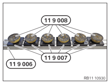
- Prepare the special tools 0 494 371 (11 9 006), 0 494 372 (11 9 007)
and 0 494 373 (11 9 008)
as shown.
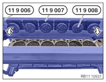
- Position the special tools 0 494 371 (11 9 006), 0 494 372 (11 9 007)
and 0 494 373 (11 9 008)
in the direction of arrow in the center on the cylinder head.
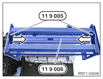
- Slide the special tool 0 494 370 (11 9 005)
in the direction of arrow over the edge of the special tool 0 494 371 (11 9 006).
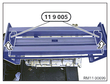
- Lock special tool 0 494 370 (11 9 005) in arrow direction.
- Turn special tool 0 494 362 (11 9 000)
and the cylinder head by 180°.
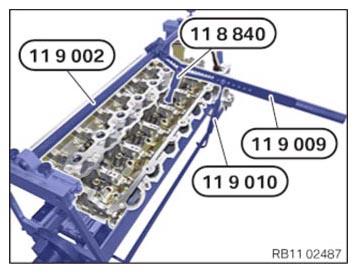
- Mount special tool 0 494 367 (11 9 002).
- Align special tool 0 494 374 (11 9 009) in direction of valve axis. Select the corresponding groove using special tool 0 496 143 (11 8 840).
- Press down the valve spring on the upper spring cup with the special tools 0 494 374 (11 9 009) and 0 496 143 (11 8 840).
- The valve spring can be maintained in pressed down installation position with the special tool 0 494 375 (11 9 011).
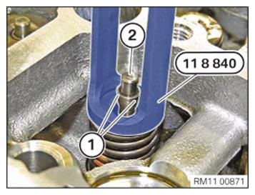
- Keep the valve spring pressed down with the special tool 0 496 143 (11 8 840).
- Remove the valve shims (1) from the valve (2) using a magnet.
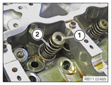
- Relieve load on valve spring.
- Remove the spring cup (1) and the valve spring (2) and position neatly in the special tool 0 495 105 (11 4 480).