Installing the cylinder head
NOTE:
TECHNICAL INFORMATION
After replacement of the engine or cylinder head: If necessary, reprogram/encode Digital Motor Electronics (DME).
Read out I level of the vehicle and the proceed accordingly.
It is imperative to observe Product and Measures Management Aftersales measure 62634754.
For further information, see the applicable BMW parts catalogue.
NOTE:
TECHNICAL INFORMATION
When replacing the cylinder head: The complete valve control and the Valvetronic servomotor are already pre-assembled for new cylinder heads.
When replacing the cylinder head: The complete valve control and the Valvetronic servomotor are already pre-assembled for new cylinder heads.
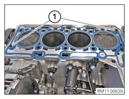
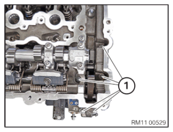
- Check the fitting sleeves (1) for damage and a correct installation location, replace if necessary.NOTE: TECHNICAL INFORMATION
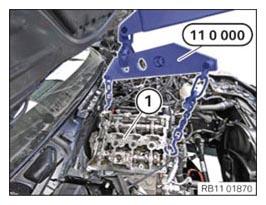
Conduct the following operation with the assistance of a second person. - Install the cylinder head (1) and the exhaust turbocharger with the workshop crane and the special tool 0 490 561 (11 0 000)
.
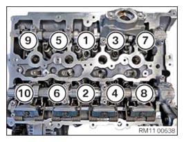
- Replace screws (1) to (10).
Parts: Screws
- Make sure that all threaded holes in the engine block are free of coolant, engine oil or other contaminations.
- Position the screws in the sequence (1) to (10).
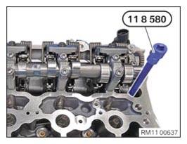
- Tighten cylinder head bolts using special tools 0 490 504 (00 9 120)
and 0 495 747 (11 8 580)
in sequence (1) to (10).TIGHTENING TORQUES SPECIFICATION
Cylinder head to crankcase M11x1.5x188 11.9
Fit new cylinder head bolts.1. Jointing torque 30 Nm 2. Angle of rotation 90° 3. Angle of rotation 180° M11x1.5x188 13.9
Fit new cylinder head bolts.1. Jointing torque 30 Nm 2. Jointing torque 50 Nm 3. Angle of rotation 180° 4. Angle of rotation 180° - Install and tighten down screws (1).TIGHTENING TORQUES SPECIFICATION
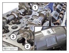
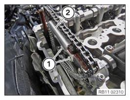
Cylinder head bolt to timing case cover M8x40 Tightening torque 20 Nm - Secure the intake camshaft with an open-end spanner (1).
- Position the camshaft sensor wheel (3) and tighten the bolt (2).TIGHTENING TORQUES SPECIFICATION
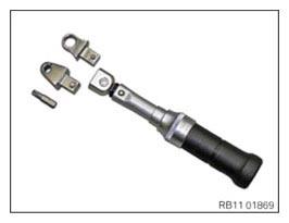
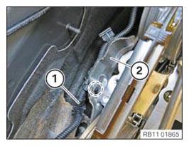
Camshaft sensor wheel to intake camshaft M6 Tightening torque 10 Nm - Use the tool as shown for the next operation to tighten the screw connections of the grounding cable and the acoustic cover.
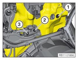
- Position acoustic cover and tighten with screw (1).TIGHTENING TORQUES SPECIFICATION
Acoustic cover, rear bottom on cylinder head M6x 16 Tightening torque 8 Nm - Lay wiring harness correctly and secure with the screw (3).TIGHTENING TORQUES SPECIFICATION
Cable clip on rear cylinder head/transmission M6x20 Tightening torque 8 Nm - Position the grounding cable and tighten it with the bolt (2).TIGHTENING TORQUES SPECIFICATION
Grounding cable on cylinder head M6x16 Tightening torque 8 Nm - Clip in the cable (1) in the highlighted area on the acoustic cover (2).
- Mount the slide rail (2).
- Tighten the screws (1).TIGHTENING TORQUES SPECIFICATION
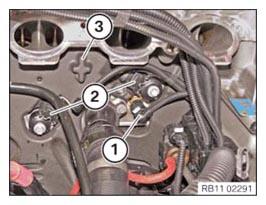
Sliding rail to cylinder head M6x16 Tightening torque 8 Nm - Position the engine encapsulation (3) correctly.
- Connect connectors (1) and (2) lock.NOTE: TECHNICAL INFORMATION
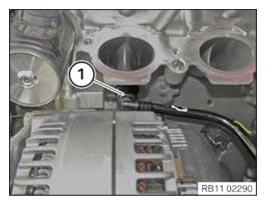
Make sure that the connections are locked correctly. The locks must engage audibly. - Lock the coolant line (1) in place and plug onto the cylinder head.
Follow-up Work
- Refer to BLOCKING THE CAMSHAFTS
- Refer to INSTALLING THE INTAKE ADJUSTER .
- Refer to INSTALL VANOS CENTRAL VALVE OF THE INTAKE SIDE .
- Refer to INSTALL EXHAUST CAMSHAFT ADJUSTER .
- Refer to INSTALL VANOS CENTRAL VALVE OF THE EXHAUST SIDE .
- Refer to PRELOAD TIMING CHAIN .
- Refer to TIGHTENING THE VANOS CENTRAL VALVE .
- Refer to DISASSEMBLING ALL SPECIAL TOOLS
- Refer to CHECKING CAMSHAFT TIMING .
- Refer to INSTALLING THE THERMOSTAT ON THE TRANSMISSION OIL LINES .
- Refer to SECURING THE OIL SUMP ACOUSTIC COVER .
- Refer to INSTALLING CYLINDER HEAD COVER .
- Refer to INSTALLING BOTH ACTUATORS .
- Refer to PREPARE THE INJECTORS FOR INSTALLATION .
- Refer to INSTALLING THE RAIL
- Refer to PREPARE FOR THE INSTALLATION OF THE HIGH PRESSURE PUMP
- Refer to INSTALL HIGH PRESSURE PUMP .
- Refer to INSTALLING FUEL DELIVERY LINE .
- Refer to INSTALLING THE HIGH-PRESSURE LINE BETWEEN THE HIGH-PRESSURE PUMP AND THE HIGH-PRESSURE RAIL .
- Refer to INSTALLING ALL SPARK PLUGS .
- Refer to INSTALLING THE IGNITION COILS .
- Refer to INSTALLING THE INTAKE PLENUM .
- Refer to INSTALLING THE TANK VENT VALVE .
- Refer to INSTALL CONTROL UNIT BRACKET .
- Refer to INSTALL THE INTEGRATED POWER SUPPLY MODULE (PDM) .
- Refer to INSTALLING THE DME CONTROL UNIT .
- Refer to INSTALL THE COOLANT FEED LINE FOR THE EXHAUST TURBOCHARGER (COOLANT RETURN LINE REMOVED)
- Refer to ATTACH THE OIL RETURN LINE FOR THE EXHAUST TURBOCHARGER .
- Refer to INSTALLING OIL FEED LINE FOR EXHAUST TURBOCHARGER (ENGINE ENCAPSULATION REMOVED)
- Refer to INSTALL THE ACOUSTIC COVER FOR THE ENGINE AT THE FRONT .
- Refer to INSTALL FRONT ENGINE ENCAPSULATION .
- Refer to INSTALLING AUXILIARY COOLANT PUMP FOR THE EXHAUST TURBOCHARGER .
- Refer to CONNECT THE COOLANT LINE OF HIGH-TEMPERATURE COOLANT CIRCUIT
- Refer to CONNECT THE COOLANT LINES FOR THE LOW-TEMPERATURE COOLANT CIRCUIT
- Refer to INSTALL THE COOLANT RETURN LINE FOR THE EXHAUST TURBOCHARGER (AUXILIARY COOLANT PUMP REMOVED)
- Refer to INSTALL CATALYTIC CONVERTER .
- Refer to INSTALLING THE COMPLETE EXHAUST SYSTEM .
- Refer to INSTALL THE REAR AXLE COVER .
- Refer to IF INSTALLED: INSTALL THE TORSION STRUT ON THE RIGHT AND ON THE LEFT AS NEEDED .
- Refer to INSTALL THE CONNECTING SUPPORTS ON THE TUNNEL
- Refer to INSTALLING THE MONITORING OXYGEN SENSOR .
- Refer to INSTALL FRONT OXYGEN SENSOR .
- Refer to INSTALLING THE HEAT SHIELD ON THE EXHAUST MANIFOLD .
- Refer to INSTALL THE CYLINDER HEAD COVER ACOUSTIC COVER
- Refer to INSTALL CHARGE AIR LINE
- Refer to INSTALLING CLEAN AIR PIPE .
- Refer to INSTALLING INTAKE SILENCER HOUSING .
- Refer to INSTALL RESONATOR .
- Refer to INSTALLING CENTER BULKHEAD LOWER SECTION
- Refer to INSTALLING ACOUSTIC COVER AT REAR .
- Refer to FASTENING HIGH-VOLTAGE CABLES ON THE ELECTRICAL MACHINE ELECTRONICS .
- Refer to INSTALLING LEFT SEALING FRAME
- Refer to INSTALLING RIGHT SEALING FRAME
- Refer to INSTALLING THE CENTER BULKHEAD UPPER PART
- Refer to INSTALL BOTH TENSION STRUTS FROM SPRING STRUT DOME
- Refer to INSTALLING COWL PANEL COVER .
- Refer to INSTALL LEFT AND RIGHT WIPER ARM .
- Refer to INSTALL THE COVER OF THE ENGINE COMPARTMENT ON THE REAR LEFT .
- Refer to INSTALL THE SEAL FOR THE BONNET .
- Refer to FILLING THE LOW-TEMPERATURE COOLING SYSTEM WITH THE VACUUM FILLER DEVICE
- Refer to FILL THE HIGH-TEMPERATURE COOLING SYSTEM WITH THE VACUUM FILLER DEVICE
- Refer to TOPPING UP THE MOTOR OIL
- Refer to CONNECT DIAGNOSIS SYSTEM; IF NECESSARY ENCODE AND PROGRAM I LEVEL .
- Refer to BLEEDING THE LOW-TEMPERATURE COOLING SYSTEM .
- Refer to BLEED THE HIGH-TEMPERATURE COOLANT CIRCUIT .
- Refer to CHECKING/TOPPING UP OIL LEVEL IN AUTOMATIC TRANSMISSION .
- Refer to CHECK ENGINE OIL LEVEL .
- Refer to INSTALL ACOUSTIC COVER .
- Refer to INSTALLING THE REAR STIFFENING PLATE .
- Refer to INSTALLING THE UNDERBODY PROTECTION OF THE STEERING GEAR OR THE FRONT STIFFENING PLATE .
- Refer to INSTALL FRONT UNDERBODY PROTECTION AND/OR FRONT STIFFENING PLATE .
- Refer to TAKE BONNET OUT OF THE SERVICE POSITION .