Disassemble cylinder head on left and assemble
Prerequisite
- Ignition is switched off.
Risk of burning!
- Perform all work only on components that have cooled down.
Danger! Immobilization period-threatening injuries!
- Observe safety instructions on raising the vehicle using a vehicle hoist.
- For additional information see: RAISE THE VEHICLE USING A VEHICLE LIFT .
Risk of short circuits! Risk of fire!
- Make sure that there is no charger connected to the jump start terminal in the engine compartment.
- Detach battery ground lead from battery.
- For auxiliary batteries: Detach battery minus cables from all auxiliary batteries.
Risk of fire! Danger of explosion!
- When working on the fuel system, make sure the workstation has sufficient ventilation, e.g., by means of extraction.
- Tightly seal off open lines and connections; collect any leakage fuel directly at the point of exit.
- No fire, sparks, open flames or smoking.
Injury hazard!
- Note component's center of gravity.
- Support component using a jack.
- Secure component against falling off the jack.
Careless handling of tools and sharp-edged components.
Scratches, surface damage.
- Protect working area.
- Handle tools and components carefully.
Collect and dispose of emerging fluids. Observe country-specific waste disposal regulations.
When the engine is stopped after the completion of trip, it may be necessary to run the electric fan. In rare cases, operation of the electric fan can last up to 11 min. This protects the components. In this case, replacing the electric fan will not remedy the problem!
Preliminary work
- Refer to SUCTION THE AIR CONDITIONING .
- Refer to REMOVE THE CONNECTING SUPPORT FROM THE TUNNEL .
- Refer to REMOVING CENTER REAR UNDERSHIELD .
- Refer to REMOVE EXHAUST SYSTEM .
- Refer to REMOVING THE RETAINING BRIDGE .
- Refer to REMOVING THE RETAINING BRIDGE IN VEHICLES WITH A GASOLINE PARTICULATE FILTER .
- Refer to PARTIALLY REMOVING THE LEFT LAMBDA OXYGEN SENSOR .
- Refer to PARTIALLY REMOVING THE LAMBDA OXYGEN SENSOR .
- Refer to REMOVING THE LEFT OXYGEN SENSOR MONITOR .
- Refer to REMOVING THE RIGHT OXYGEN SENSOR MONITOR .
- Refer to REMOVE UPPER HEAT SHIELD .
- Refer to REMOVING THE LEFT HEAT SHIELD .
- Refer to REMOVE RIGHT HEAT SHIELD .
- Refer to REMOVE THE COVER OF THE REAR RIGHT ENGINE COMPARTMENT .
- Refer to REMOVE THE COVER OF THE ENGINE COMPARTMENT AT THE REAR LEFT
- Refer to REMOVE LEFT AND RIGHT WIPER ARM .
- Refer to REMOVE THE COWL COVER .
- Refer to REMOVING TRAILING LINK AT SPRING BOLT .
- Refer to REMOVING THE COWL UPPER PART IN THE CENTER .
- Refer to LIFTING THE HEAT SHIELD .
- Refer to REMOVING THE CATALYTIC CONVERTER FOR CYLINDERS 5 TO 8 .
- Refer to REMOVING THE COVER ON LEFT AND RIGHT IN THE ENGINE COMPARTMENT AT THE TOP .
- Refer to REMOVING LEFT INTAKE FILTER HOUSING WITH LEFT FRONT-END STRUT .
- Refer to REMOVING RIGHT INTAKE FILTER HOUSING WITH RIGHT FRONT-END STRUT .
- Refer to REMOVE FRONT CROSS CONNECTION .
- Refer to REMOVE THE REAR TOP CROSS CONNECTION .
- Refer to REMOVE FAN COWL .
- Refer to REMOVE DRIVE BELT .
- Refer to RELEASING LEFT CHARGE AIR LINE PARTIALLY .
- Refer to PARTIALLY RELEASING THE RIGHT CHARGE AIR LINE .
- Refer to REMOVING THE FRONT RIGHT LOWER WHEEL ARCH COVER .
- Refer to REMOVING THE LEFT FRONT BOTTOM WHEEL ARCH COVER .
- Refer to REMOVE THE FRONT UNDERBODY PROTECTION OR FRONT THRUST FIELD .
- Refer to REMOVING THE UNDERBODY PROTECTION OF THE STEERING GEAR AND THRUST FIELD RESPECTIVELY .
- Refer to DRAINING COOLANT .
- Refer to DRAINING THE COOLANT FOR THE LOW-TEMPERATURE COOLANT CIRCUIT .
- Refer to REMOVE THE COOLANT EXPANSION TANK FOR THE LOW-TEMPERATURE COOLANT CIRCUIT (CHARGE AIR COOLER) .
- Refer to REMOVE BOTH CHARGE AIR COOLERS .
- Refer to REMOVE THE CLEAN AIR PIPE OF CYLINDER BANK 1 .
- Refer to REMOVE THE CLEAN AIR PIPE OF CYLINDER BANK 2 .
- Refer to REMOVING THE IGNITION COILS OF CYLINDERS 1 AND 5 .
- Refer to REMOVING IGNITION COIL OF CYLINDER BANK 2 .
- Refer to REMOVING FUEL DELIVERY LINE .
- Refer to REMOVE LEFT HIGH PRESSURE PUMP .
- Refer to REMOVE THE HIGH-PRESSURE RAIL ON THE LEFT .
- Refer to REMOVE THE INJECTORS FOR CYLINDERS 5 TO 8 .
- Refer to REMOVE THE EXHAUST TURBOCHARGER FOR THE CYLINDERS 5 TO 8 .
- Refer to REMOVING VANOS SOLENOID ACTUATOR, EXHAUST OF CYLINDER BANK 2 .
- Refer to REMOVING VANOS SOLENOID ACTUATOR, INTAKE OF CYLINDER BANK 2 .
- Refer to REMOVE LEFT CYLINDER HEAD COVER .
- Refer to REMOVING THE PRESSURE LINE BETWEEN THE EVAPORATOR AND THE AIR CONDITIONING CONDENSER .
- Refer to REMOVE THE SEALING CAP ON THE CYLINDER HEAD OF THE CYLINDER BANK 2 .
- Refer to MOVING THE CRANKSHAFT TO THE INSTALLATION POSITION TO ADJUST THE TIMINGS .
- Refer to CHECK THE VANOS ADJUSTER OF CYLINDER BANK 2 .
- Refer to RELAXING CHAIN TENSIONER ON BANK 2 FOR CHECKING OR SETTING TIMING .
- Refer to REMOVING HYDRAULIC CHAIN TENSIONER OF CYLINDER BANK 2 .
- Refer to PRELOADING THE TIMING CHAIN OF CYLINDER BANK 2 .
- Refer to FIXING THE ENGINE IN THE INSTALLATION POSITION ON CYLINDER 1 (SET VALVE TIMINGS) .
- Refer to REMOVING BOTH LEFT VANOS ADJUSTERS .
- Refer to REMOVING SPECIAL TOOL FOR FIXING CAMSHAFTS IN POSITION ON BANK 2 .
- Refer to REMOVING SPECIAL TOOL TO PRETENSION TIMING CHAIN ON CYLINDER BANK 2 .
- Refer to REMOVE LEFT CYLINDER HEAD .
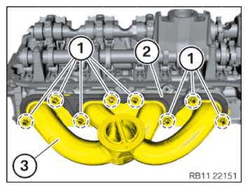
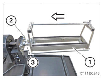
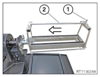
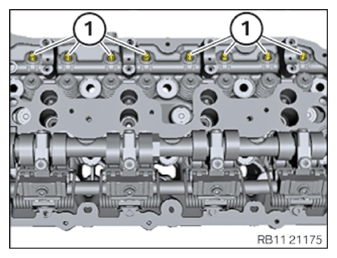
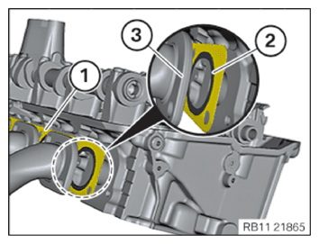
Removing the stud bolt on the left cylinder head (cylinder head removed)
- Loosen nuts (1).
- Guide out and remove the sliding frame (2).
- Guide out and remove the right exhaust manifold (3).
- Remove the exhaust manifold seal (1).
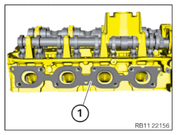
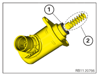
- Remove the stud bolt (1).
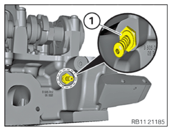
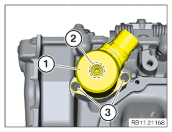
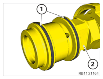
Removing the engine venting connector of cylinder bank 2
- Release venting connector (1).
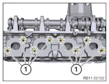
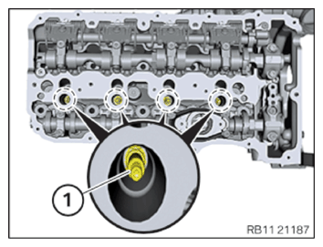
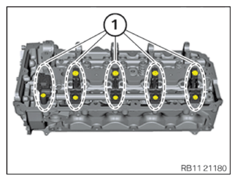
Remove spark plugs of bank 2, cylinder head removed
Injury hazard!
- Collect dirt particles, e.g. when blowing out, use cloth to do so.
- Wear safety goggles.
Clean spark plug slot with compressed air.
The spark plug shaft must be cleaned using compressed air after having removed the ignition coils and before removing the spark plugs. After having removed the spark plugs, once again check the sealing surface for contamination and (if necessary) clean using a moist cloth or clean using compressed air.
Deposits that are not removed according to instructions may enter the combustion chamber and lead to uncontrolled combustion. Remaining deposits on the spark plug sealing surfaces may lead to leaks and the spark plugs may come loose during engine operation.
Spark plug threads must not be greased or oiled. Insufficiently tightened spark plugs may cause leaks and the sparks plugs may come loose during engine operation.
- Unscrew the spark plugs with the special tool 0 495 560 (12 1 220) and an extension with joint.
Flexible ratchet extensions must always be used. If rigid mounting tools are used, there is a risk of insulator breakages.
Also, do not use a variable plug connection with locking capability as this poses a risk of insulator breakages.
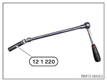
- Unscrew spark plugs (1) with special tool 0 495 560 (12 1 220) and extension with joint.
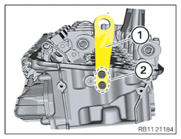
Remove the engine mounting bracket of cylinder bank 2
- Loosen screws (2).
- Remove the engine mounting bracket (1).
Attaching cylinder head of bank 2 to assembly jig, and removing and installing valves
Heavy components can lead to injury or damage.
- Remove and install heavy components with the aid of another person/other persons.
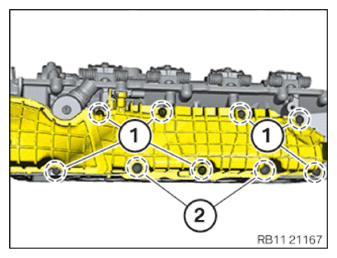
Remove the left intake plenum (cylinder head removed)
- Loosen screws (1).
- Loosen screws (2).
- Guide out right intake plenum.
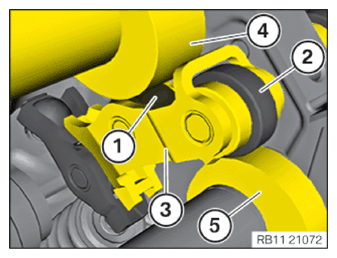
Removing the left Valvetronic servomotor (cylinder head removed)
- Loosen screws (3).
- Turn Valvetronic servomotor eccentric shaft (2) counterclockwise to loosen and remove the Valvetronic servomotor (1).
Installing the cylinder head of cylinder bank 2 on the assembly jig
Heavy components can lead to injury or damage.
- Remove and install heavy components with the aid of another person/other persons.
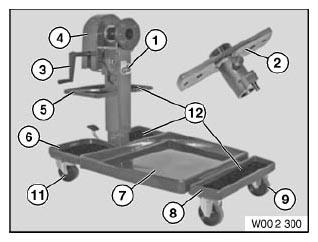
- Get the set of special tools 0 495 187 (00 2 300) ready.
| Number | Description |
|---|---|
| 1 | Assembly jig |
| 2 | Flange |
| 3 | Crank |
| 4 | cover panel |
| 5 | shelf |
| 6 | Rear shaped part |
| 7 | Collecting vessel |
| 8 | Front shaped part |
| 9 | Front wheel |
| 10 | Rear wheel with stop |
| 11 | Rubber mat |
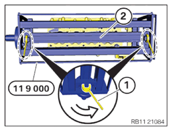
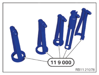
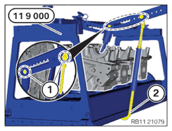
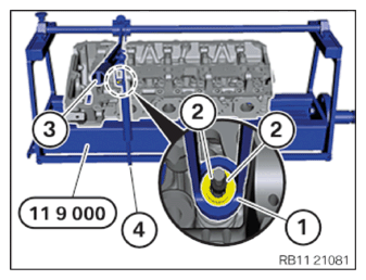
- Get the set of special tools 0 494 362 (11 9 000) ready.
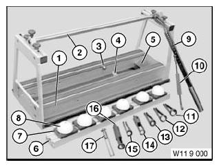
| Number | Description |
|---|---|
| 1 | Device |
| 2 | Rod |
| 3 | Adapter |
| 4 | Lug |
| 5 | Quick tensioning device |
| 6 | Aluminum frame insert |
| 7 | Shaped part |
| 8 | Plastic shaped part |
| 9 | lever |
| 10 | hook |
| 11 | Valve spring cage |
| 12 | Valve spring cage |
| 13 | Valve spring cage |
| 14 | Valve spring cage |
| 15 | Valve spring cage |
| 16 | Valve spring cage |
| 17 | Valve spring cage |
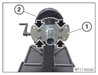
- Position the flange (1) on the assembly jig (2).
- Tighten screws (arrows).
| Flange to assembly jig | ||
| M14X30 | Tightening torque | 135 Nm |
- Feed in the device (1) on the flange (2) in direction of arrow and install.
- Make sure that the lock (3) engages audibly.
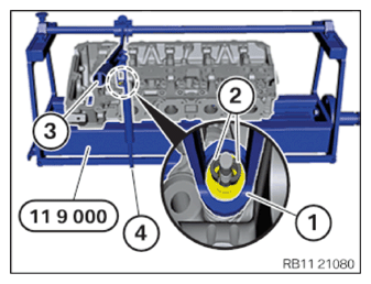
- Loosen screw (1).
- Feed out rod (2) in arrow direction and set aside.
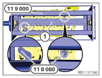
- Keep the screws from the set of special tools 0 496 408 (11 8 080) ready.
- The washers of the cylinder head bolts (1) must be used.
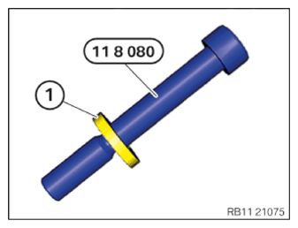
- Apply the cylinder head (1) hand-tight on the special tool 0 494 362 (11 9 000) in the attachment point area using the screws from the set of special tools 0 496 408 (11 8 080) .
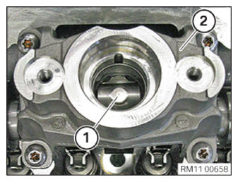
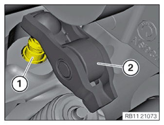
Removing the exhaust camshaft of cylinder bank 2
- Remove the roller tappet (1) from high pressure pump bracket (2).
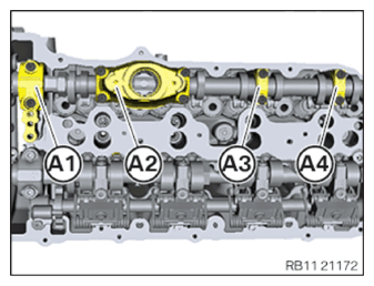
- Mark the guide bearing shells of the exhaust camshaft from (A1) to (A4) as shown in the graphic.
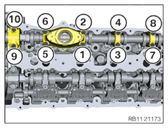
- Release the screws of the guide bearing in the order (1) to (10) by half a rotation at a time.
- Remove the guide bearing shells of the exhaust camshaft.
- Remove the exhaust camshaft.
 Courtesy of BMW OF NORTH AMERICA, INC.
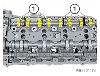
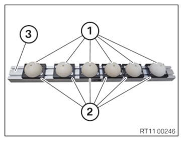
Removing the roller cam follower from the exhaust side of cylinder bank 2
- Detach and remove the roller cam followers (1) on the exhaust side from hydraulic valve clearance compensating elements (arrows).
- Place all roller cam followers in order in special tool 0 495 105 (11 4 480) .
Removing hydraulic valve clearance compensating elements of the exhaust side of cylinder bank 2
- Pull all exhaust hydraulic valve clearance compensating elements of the exhaust side (1) up and off.
- Place all hydraulic valve clearance compensating elements in proper order on the special tool 0 495 105 (11 4 480) .
Remove torsion springs
Prerequisite
If the Valvetronic servomotor is installed, the eccentric shaft must be released via the Valvetronic servomotor.
Injury hazard!
- The use of the specified special tool (tool) is mandatory.
- Carry out the described steps properly.
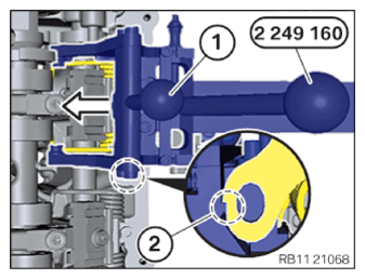
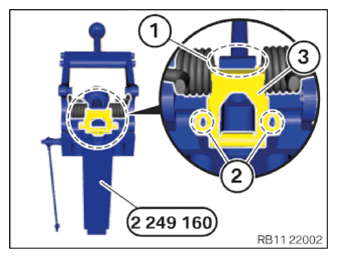
- The modified locking rods 2 411 031 must be installed on the special tool 2 249 160.
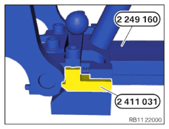
- Position special tool 2 249 160 at a downward angle on the torsion spring panel (2).
The lug (1) should be positively locked with the torsion spring panel (2).
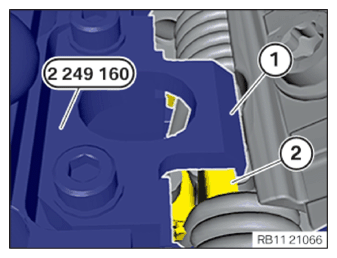
- The guide pins (2) in the special tool 2 249 160 should be positively locked with the recesses in the torsion spring panel (1).
- Press lever (1) on the special tool 2 249 160 in the direction of arrow until the latch mechanisms (2) lock.
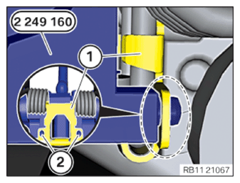
- Release bolt on the plate of the torsion spring in the area (1).
- Guide out special tool 2 249 160 (2) with the torsion spring and the panel of the torsion spring.
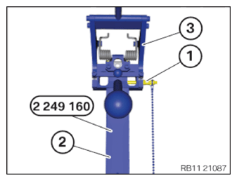
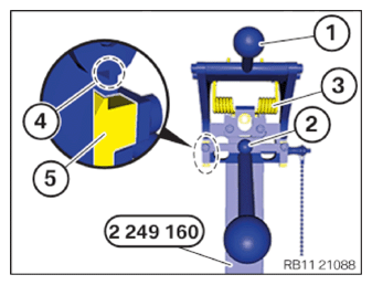
- Connect separate components of the special tool 2 249 160
(3) to (2) and secure with the locking pin (1).
The locking pin (1) should audibly engage.
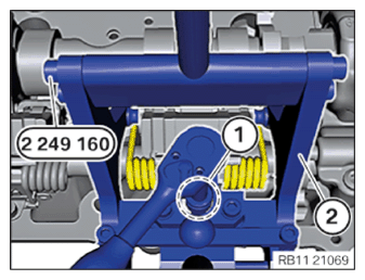
- Clamp special tool 2 249 160 in a standard vice at area (2).
- Use the lever (1) to push special tool 2 249 160 forward to pretension the torsion springs (3).
- Pull lever (2) down to release the retaining pins (5) from the anti-twist locks (4).
- Carefully release tension on the lever (1) on the special tool 2 249 160.
- Remove the torsion spring with the lock plate (3) and place it in the special tool 0 495 105 (11 4 480) in an ordered position.

- Repeat steps for all torsion springs.
Twist camshaft if necessary.
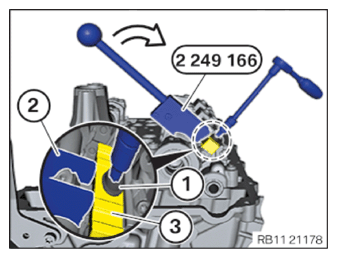
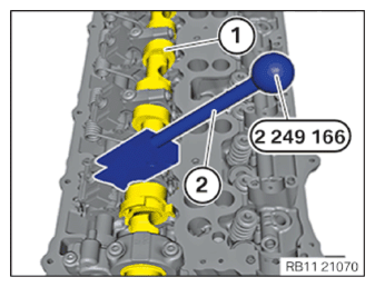
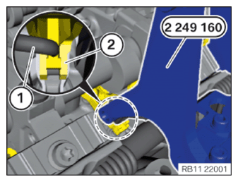
Remove the sliding block of cylinder bank 2
- Position the special tool 2 249 166 on the intake camshaft (1) in the area of the sliding block (2) to be disassembled.
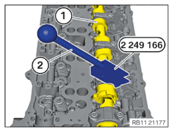
- Preload the sliding block (3) with the special tool 2 249 166 (2) in direction of arrow.
- Loosen screw (1).
- Remove the gate (3) and place it arranged in order into 0 495 105 (11 4 480) .
- Repeat the step for all the gates.
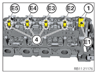
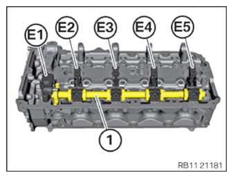
Removing the intake camshaft of cylinder bank 2
- Mark the guide bearing shells of the intake camshaft from (E1) to (E5) as shown in the graphic.
- Release the screws of the guide bearing with the item numbers (1) and (4) in several steps by half a rotation at a time.
- Remove the guide bearing shells.
- Remove the intake camshaft.
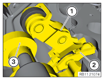
Remove the intermediate lever of the intake side
- Feed out the intermediate lever (1) upward from the roller cam follower (2) and the cam (3) of the eccentric shaft.
- Repeat the step for all intermediate levers (1).
Removing the roller cam follower of the intake camshaft
- Release and remove the roller cam follower (2) on the intake side from the hydraulic valve clearance compensating element.
- Place all roller cam followers in order in special tool 0 495 105 (11 4 480) .
- Remove all hydraulic valve clearance compensating elements (1) to the top.
- Place all hydraulic valve clearance compensating elements into the special tool 0 495 105 (11 4 480) along with the roller cam followers in order.
Remove the eccentric shaft of cylinder bank 2
Contaminant or foreign body.
Contamination can result in malfunctions, loss of function or leaks.
- Adhere to the utmost cleanliness.
- Protect components from contamination e.g. by covering.
- Close off line connections with seal plugs.
- Release all the screws in the marked areas (1).
- Twist the eccentric shaft (2) counterclockwise.
- Label the bearing brackets as shown in the graphic.
- Orderly set down bearing brackets (E1) to (E5) in the special tool 0 495 105 (11 4 480) .
- Guide out the eccentric shaft (2) toward the top and remove it.
Set up cylinder head of cylinder bank 2 on special tool 119000
Heavy components can lead to injury or damage.
- Remove and install heavy components with the aid of another person/other persons.
- Prepare plastic shaped parts (1) with the shaped parts (2) and aluminum frame insert (3).
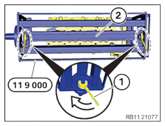
- Quick clamping devices (1) on special tool 0 494 362 (11 9 000) (2) must be unlocked.
- Insert aluminum frame insert (2).
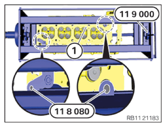
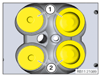
- Position cylinder head on special tool 0 494 362 (11 9 000) .
The valves in area (2) must be aligned with the plastic elements (1).
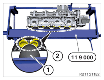
- Cylinder head (1) on special tool 0 494 362 (11 9 000) must be hand-tightened in the area of the attachment points with screws from the set of special tools 0 496 408 (11 8 080) .
- Lock quick clamping device (1) on special tool 0 494 362 (11 9 000) (2) in arrow direction.
- Select the correct valve spring cage from the set of special tools 0 494 362 (11 9 000) .
- Complete special tool 0 494 362 (11 9 000) .
- Select suitable position on the lever of the valve spring cage (1) and secure hand-tight with the screws.
- Hook with damper (2) can be fixed on special tool 0 494 362 (11 9 000) for easier disassembly of the valve shims.
Remove valves
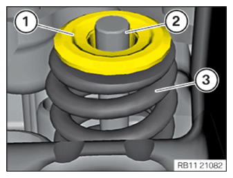
- Position valve spring cage (1) on the valve head.
- Push special tool 0 494 362 (11 9 000) down on the lever (3) and attach on the hook (4).
- Remove valve shims (2) with magnet.
- Detach hook (4).
- Relieve lever (3).
- Remove valve spring cup (1).
- Remove valve spring (3) and place it arranged in order in the special tool 0 495 105 (11 4 480)
.
Observe color coding and direction of installation and mark and identify where required.
- When replacing the valves, the cylinder head must be detached from the cylinder head 0 494 362 (11 9 000) .
- Repeat step for all valves.
Replacing the valve stem seals
Contaminant or foreign body.
Contamination can result in malfunctions, loss of function or leaks.
- Adhere to the utmost cleanliness.
- Protect components from contamination e.g. by covering.
- Close off line connections with seal plugs.
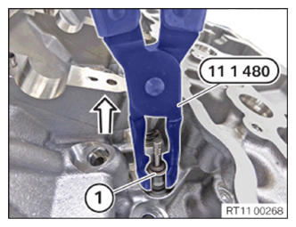
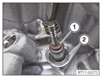
- Disassemble the valve stem seal (1) in arrow direction with the special tool 0 490 796 (11 1 480) .
- Remove oil and dirt from the contact surface (1).
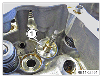
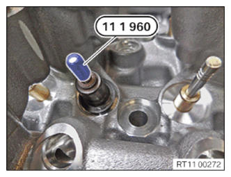
- During installation of the valve stem seal, use the special tool 0 490 797 (11 1 960) .
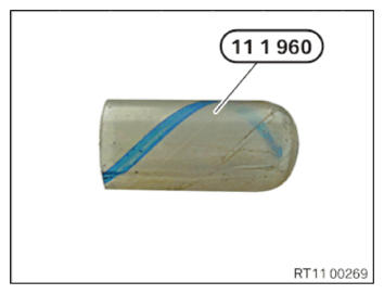
- Insert and install special tool 0 490 797 (11 1 960) on the valve (1).
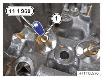
- Insert and install valve stem seal (1) on the special tool 0 490 797 (11 1 960) .
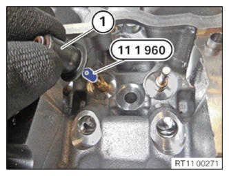
- Guide the special tool 0 490 797 (11 1 960) out and remove.
- Press the valve stem seal (1) with the special tool 0 493 249 (11 6 380) onto the cylinder head until the stop.
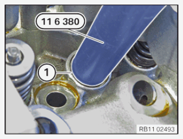
- Make sure the valve stem seal (1) is properly positioned on the cylinder head (2).
Installing valves
- When replacing the valves, the cylinder head must be fastened on the special tool 0 494 362 (11 9 000) .
- Observe the color coding and direction of installation.
Position the valve spring (3).
- Position the valve spring cup (1).
- Position valve spring cage (1) on the valve head.
- Push special tool 0 494 362 (11 9 000) down on the lever (3) and attach on the hook (4).
- Insert the valve shims (2) with a magnet or screwdriver.
- Detach hook (4).
- Relieve lever (3).
- Repeat step for all valves.
Checking the valves for tightness
Risk of fire! Danger of explosion!
- When working on the fuel system, make sure the workstation has sufficient ventilation, e.g., by means of extraction.
- Tightly seal off open lines and connections; collect any leakage fuel directly at the point of exit.
- No fire, sparks, open flames or smoking.
Hazardous to health!
- Note and follow safety instructions on containers.
- Conduct all work in appropriate personal protective equipment only.
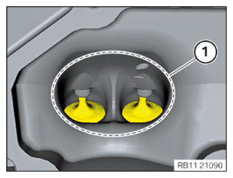
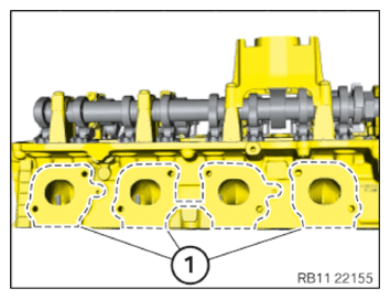
- Coat all intake valves with fuel in area (1) on the cylinder head.
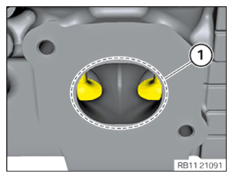
- Coat all exhaust valves with fuel in area (1) on the cylinder head.
Check
- Does fuel escape from valves (1) and (2) on the cylinder head?
Result
» No fuel escapes from the valves or valve seats.
Measure
- Continue the repair with the next step.
Result
» Fuel escapes from the valves or valve seats.
Measure
- Clean valves, countersink and replace if necessary.
Installing cylinder bank 2 eccentric shaft
- Coat the bearing positions of the eccentric shaft with motor oil.
- Insert the eccentric shaft (2) from below and install.
- Pay attention to the installation locations of the guide bearing shells (E1) to (E5).
- Position bearing brackets as shown in the illustration.
Contaminant or foreign body.
Contamination can result in malfunctions, loss of function or leaks.
- Adhere to the utmost cleanliness.
- Protect components from contamination e.g. by covering.
- Close off line connections with seal plugs.
- Tighten all screws in the marked areas (1).
| Eccentric shaft bearing brackets | ||
| Screw M6 | Tightening torque | 10 Nm |
Releasing tension on special tool 119000
Heavy components can lead to injury or damage.
- Remove and install heavy components with the aid of another person/other persons.
- Release quick clamp device (1) from the special tool 0 494 362 (11 9 000) (2) in the direction of the arrow.
- Remove aluminum frame insert (2).
Installing the roller cam follower of the intake camshaft
- If a new hydraulic valve clearance compensating element has not been installed, install in the same position.
- Install all hydraulic valve clearance compensating elements (1) downward.
- If the roller cam followers are not being replaced, install the roller cam followers in the same position.
- Install the roller cam follower (2).
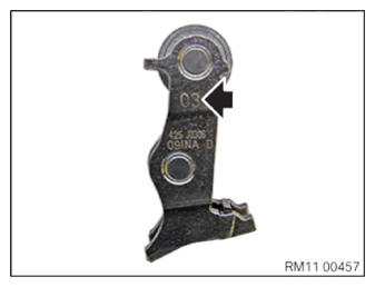
Checking the intermediate lever classification
All intermediate levers are classified. Only one classification may be used per engine.
All intermediate levers must be reinstalled in the same positions in an engine which has already been in use.
- Checking the intermediate lever classification (arrows).
Installing intermediate lever on intake side
- Position intermediate lever (1) so that it contacts roller cam follower (2) and cam of eccentric shaft (3).
- Repeat the step for all intermediate levers (1).
Installing intake camshaft of cylinder bank 2
- Plastic rings (1) are maintenance free and do not need to be replaced.
- Check plastic rings for damage, replace if necessary.
The rocker arms may slip slightly when the camshaft is positioned. Make sure rocker arms are correctly positioned on the hydraulic valve clearance compensating elements and on valves.
- Position intake camshaft.
- When screwing the camshafts, make sure the valves have free movement.
- Position guide bearing shells according to marks (E1) to (E5).
- Join the screws of the guide bearings with position numbers (1) and (4) in multiple steps by one half turn at a time until flush.
- Tighten the screws (1).
| Intake/exhaust camshaft | ||
| M6 | Tightening torque | 10 Nm |
- Tighten down screws (4).
| Intake/exhaust camshaft | ||
| M6 | Tightening torque | 10 Nm |
- All intermediate levers (3) must rest correctly on the idler pulley (1) and on the camshaft (4).
- All intermediate levers (3) must rest correctly on the idler pulley (2) and on the eccentric shaft (5).
Installing the sliding block of cylinder bank 2
- Remove the oil and dirt from the sliding block (3).
- Position the sliding block (3) and abut with the screw (1).
- Position the special tool 2 249 166 on the intake camshaft (1) in the sliding block (2) area.
- Preload the sliding block (3) with the special tool 2 249 166 (2) in direction of arrow.
- Tighten down screw (1).
| Sliding block on cylinder head | ||
| Screw M7x35 10.9 | Tightening torque | 20.5 Nm |
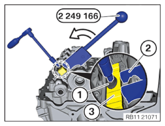
- Relieve the special tool 2 249 166 (1) and feed it out of the camshaft (2) and place aside.
- Repeat the step for all the gates.
Installing torsion springs
Injury hazard!
- The use of the specified special tool (tool) is mandatory.
- Carry out the described steps properly.
- Position the torsion springs (3) on the special tool 2 249 160.
The lug in area (1) must be positively locked with the torsion spring panel (3).
The guide pins (2) in the special tool 2 249 160 must be positively locked with the recesses in the torsion spring panel (3).
- Connect individual parts of the special tool 2 249 160
(3) to (2) and secure with the locking pin (1).
The locking pin (1) should audibly engage.
- Clamp special tool 2 249 160 in a standard vice at area (2).
- Use the lever (1) to push special tool 2 249 160 forward to pretension the torsion springs (3).
- The retaining pins (5) should be secured to the detent (4) on both sides.
- Do not operate the release lever (2).
- Feed in the special tool 2 249 160 with the torsion spring.
- Position torsion springs in the intermediate levers on the cylinder head.
The ends of the torsion springs (1) must be located in the recesses of the intermediate lever (2).
- Tighten screw at area (1) on the torsion spring panel.
| Torsion spring on cylinder head | ||
| M6x20 screw | Tightening torque | 8.8 Nm |
- The special tool 2 249 160 (2) must be pre-tensioned.
- Press lever (1) on the special tool 2 249 160 in the direction of the arrow until the detents (2) release.

- Press the lever (1) on the special tool 2 249 160 forward to keep the torsion springs (3) tensioned.
- Pull lever (2) down to release the retaining pins (5) from the anti-twist locks (4).
- Carefully release tension on the lever (1) on the special tool 2 249 160.
- Remove the special tool 0 495 105 (11 4 480) .
- Repeat steps for all torsion springs.
Twist camshaft if necessary.
Installing hydraulic valve clearance compensating element of the exhaust side of bank 2
- Install all exhaust hydraulic valve clearance compensating elements of the exhaust side (1) downward.
Install roller cam followers on exhaust side of cylinder bank 2
- Position roller cam followers (1) on exhaust side on the hydraulic valve clearance compensating elements.
Installing cylinder bank 2 exhaust camshaft
- Plastic rings (1) are maintenance free and do not need to be replaced.
- Check plastic rings for damage, replace if necessary.
- Position exhaust camshaft.
- Position exhaust camshaft guide bearing shell.
- Screw in guide bearing screws in the order (1) to (10) by a half turn at a time until they can no longer be tightened.
- Tighten screws in the order (1) to (10).
| Intake/exhaust camshaft | ||
| M6 | Tightening torque | 10 Nm |
Courtesy of BMW OF NORTH AMERICA, INC.- Install roller tappet (1) into the high pressure pump bracket (2).
Removing cylinder head of bank 2 from assembly jig
Heavy components can lead to injury or damage.
- Remove and install heavy components with the aid of another person/other persons.
- Release the screws 0 496 408 (11 8 080) at the special tool 0 494 362 (11 9 000) in the area of the attachment points.
- Remove the cylinder head (1).
Installing the left Valvetronic servomotor (cylinder head removed)
The work must be performed with vehicle care to prevent component damage.
- If necessary, lever the radial shaft seal (1) out of the cylinder head using a commercially available tool.
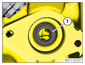
- Replace radial shaft seal (1) at front.
Parts: Radial shaft seal
- Grease the gearing on the worm drive in area (2) using lubricating grease.
Parts: lubricating grease
| Lubricating grease Longtime PD-1 |
400 g, Cartridge | 83192160340 |
- Turn the Valvetronic servomotor (1) evenly with the shaft (2) across the gearing of the worm drive as far as it will go.
- Secure screws (3).
| Valvetronic servomotor on cylinder head | ||
| M6x16-8.8 | Tightening torque | 9.6 Nm |
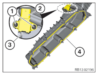
Installing the left intake plenum (cylinder head removed)
- Replace the seal (4).
Parts: Gasket
- Only during replacement of the intake plenum:
Loosen screws (1).
Unlock pressure sensor (2) on the retaining tab (3).
Remove pressure sensor (2).
Position pressure sensor (2).
Retaining tab (3) must audibly lock in.
Tighten down screws (1).
| Pressure sensor | ||
| screw | Tightening torque | 3 Nm |
- Position the left intake plenum.
- Tighten down screws (1).
| Intake plenum | ||
| M6 screw | Tightening torque | 10 Nm |
- Tighten down screws (2).
| Intake plenum | ||
| M8 screw | Tightening torque | 21.4 Nm |
Install engine mounting bracket of bank 2
- Position engine mounting bracket (1).
- Tighten screws (2).
| Engine suspension element | ||
| M8x22 screw | Tightening torque | 20 Nm |

Installing spark plugs in cylinder bank 2 (cylinder head removed)
- Insert spark plug (1) into special tool 0 496 065 (12 1 230) .
Do not drop spark plug into spark plug shaft! This can lead to a reduction of the electrode gap and can thus impair smooth running of the engine, especially in idle position.
- Make sure the spark plug does not fall into the spark plug shaft.
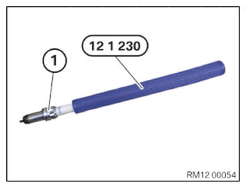
- First screw spark plugs into the engine using special tool 0 496 065 (12 1 230) and tighten manually.
Exclusively swiveling extensions may be used for the reversible ratchet. Rigid mounting tool and variable plug connections with rigid option may not be used; there is a risk that the insulator breaks.
- Tighten spark plug 1 using a torque wrench with the special tool 0 496 065 (12 1 230) and an extension with joint.
| Spark plugs | ||
| M12x1.25 | Tightening torque | 23 Nm |
Installing venting connector of cylinder bank 2
- Replace the venting connector (1).
Parts: Venting connector
- Tighten the venting connector (1).
| Venting connector/special tool to cylinder head | ||
| M8x1 Replace the venting connector. |
Tightening torque | 15 Nm |
Installing stud bolts on the left cylinder head
Prerequisite
Cylinder head is removed.
- Clean sealing surfaces (1).
- Replace the stud bolt (1).
Parts: Stud bolts
- Tighten the stud bolts (1) and check for correct fit.
| Stud bolt on cylinder head | ||
| M8x50 Replace the stud bolt. |
Tightening torque | 20 Nm |
- Replace the exhaust manifold seal (1).
Parts: Exhaust manifold seal
- Position the exhaust manifold seal (1).
- The installation position of the seal (1) must be adhered to.
The seal (1) must be installed with the side of the bead (2) (seal cavity) toward the exhaust manifold (3).
- Insert and position the exhaust manifold (3) at left.
- Position the sliding rail (2).
- Replace nuts (1).
Parts: Nuts
- Tighten nuts (1).
| Exhaust manifold to cylinder head | ||
| M8 Replace nuts. |
Tightening torque | 15 Nm |
Follow-up work
- Refer to INSTALLING THE LEFT CYLINDER HEAD .
- Refer to INSTALLING BOTH LEFT VANOS ADJUSTERS .
- Refer to REMOVING SPECIAL TOOL TO PRETENSION TIMING CHAIN ON CYLINDER BANK 2 .
- Refer to INSTALLING THE HYDRAULIC CHAIN TENSIONER OF CYLINDER BANK 2 .
- Refer to INSTALLING THE SEALING CAP ON THE CYLINDER HEAD OF CYLINDER BANK 2 .
- Refer to INSTALLING THE LEFT CYLINDER HEAD COVER .
- Refer to INSTALLING VANOS SOLENOID ACTUATOR, INTAKE OF CYLINDER BANK 2 .
- Refer to INSTALL THE VANOS SOLENOID ACTUATOR EXHAUST OF CYLINDER BANK 2 .
- Refer to INSTALL THE LEFT HIGH PRESSURE PUMP .
- Refer to INSTALLING FUEL DELIVERY LINE .
- Refer to INSTALLING THE INJECTORS FOR THE CYLINDERS 5 TO 8 .
- Refer to INSTALL THE HIGH-PRESSURE RAIL ON THE LEFT .
- Refer to INSTALL THE IGNITION COILS OF CYLINDER BANK 2 .
- Refer to INSTALLING THE IGNITION COILS OF CYLINDERS 1 AND 5 .
- Refer to INSERT THE EXHAUST TURBOCHARGER FOR THE CYLINDERS 5 TO 8 .
- Refer to INSTALLING THE CLEAN AIR PIPE OF CYLINDER BANK 2 .
- Refer to INSTALLING CLEAN AIR PIPE OF CYLINDER BANK 1 .
- Refer to INSTALLING BOTH CHARGE AIR COOLERS .
- Refer to CONNECTING THE RIGHT CHARGE AIR LINE TO THE EXHAUST TURBOCHARGER .
- Refer to CONNECTING THE LEFT CHARGE AIR LINE TO THE EXHAUST TURBOCHARGER .
- Refer to CLOSING THE HIGH-TEMPERATURE COOLANT CIRCUIT .
- Refer to INSTALL THE COOLANT EXPANSION TANK FOR THE LOW-TEMPERATURE COOLANT CIRCUIT (CHARGE AIR COOLER) .
- Refer to SEALING OFF COOLANT FOR LOW-TEMPERATURE COOLANT CIRCUIT .
- Refer to INSTALLING THE UNDERBODY PROTECTION OF THE STEERING GEAR OR THE FRONT THRUST FIELD .
- Refer to INSTALL THE FRONT UNDERBODY PROTECTION OR FRONT THRUST FIELD .
- Refer to INSTALLING THE FRONT LEFT BOTTOM WHEEL ARCH COVER .
- Refer to INSTALLING THE FRONT BOTTOM RIGHT WHEEL ARCH COVER .
- Refer to INSTALL DRIVE BELT .
- Refer to INSTALLING FAN COWL .
- Refer to INSTALL THE REAR TOP CROSS CONNECTION .
- Refer to INSTALL FRONT CROSS CONNECTION .
- Refer to INSTALLING THE RIGHT INTAKE FILTER HOUSING WITH THE RIGHT FRONT-END STRUT .
- Refer to INSTALLING LEFT INTAKE FILTER HOUSING WITH LEFT FRONT-END STRUT .
- Refer to INSTALLING THE COVER ON THE LEFT AND RIGHT IN THE ENGINE COMPARTMENT AT THE TOP
- Refer to INSTALLING THE CATALYTIC CONVERTER FOR CYLINDERS 5 TO 8 .
- Refer to RELEASING THE HEAT SHIELD .
- Refer to INSTALLING THE CENTER COWL UPPER PART .
- Refer to INSTALL TENSION STRUT ON SHOCK TOWER .
- Refer to INSTALLING WINDSHIELD PANEL COVER .
- Refer to INSTALL LEFT AND RIGHT WIPER ARM .
- Refer to INSTALL THE REAR RIGHT ENGINE COMPARTMENT COVER .
- Refer to INSTALL THE COVER OF THE ENGINE COMPARTMENT ON THE REAR LEFT .
- Refer to INSTALL RIGHT HEAT SHIELD .
- Refer to INSTALL LEFT HEAT SHIELD .
- Refer to INSTALL HEAT SHIELD, TOP .
- Refer to INSTALLING THE RIGHT OXYGEN SENSOR MONITOR .
- Refer to INSTALLING THE LEFT OXYGEN SENSOR MONITOR .
- Refer to PARTLY INSTALLING THE RIGHT LAMBDA OXYGEN SENSOR .
- Refer to PARTIALLY INSTALLING THE LEFT LAMBDA OXYGEN SENSOR .
- Refer to INSTALLING THE RETAINING BRIDGE IN VEHICLES WITH A GASOLINE PARTICULATE FILTER .
- Refer to INSTALLING THE RETAINING BRIDGE .
- Refer to INSTALL EXHAUST SYSTEM .
- Refer to INSTALLING CENTER REAR UNDERSHIELD .
- Refer to INSTALL THE CONNECTING SUPPORTS ON THE TUNNEL .
- Refer to INSTALLING THE CONTROL UNIT BRACKET FOR CYLINDERS 5 TO 8 .
- Refer to INSTALLING THE COVER OF THE LEFT DME CONTROL UNIT .
- Refer to INSTALLING CONTROL UNIT HOLDER FOR CYLINDERS 1 TO 4 .
- Refer to INSTALLING THE COVER OF THE RIGHT DME CONTROL UNIT .
- Refer to CONNECTING NEGATIVE BATTERY CABLE .
- Refer to FILL AND VENT THE LOW-TEMPERATURE COOLANT CIRCUIT .
- Refer to FILL AND VENT THE HIGH-TEMPERATURE COOLANT CIRCUIT .
- Refer to EVACUATE AND CHARGE CONDITIONING .